Striker bracket attachment structure for vehicular hood

A technology for engine hoods and engine rooms, applied in vehicle locks, vehicle parts, building structures, etc., can solve problems such as difficulty in ensuring head protection performance, difficult to ensure travel, etc., and achieve the effect of relieving the concentration of stress

Active Publication Date: 2016-08-17
KOBE STEEL LTD
View PDF7 Cites 0 Cited by
  • Summary
  • Abstract
  • Description
  • Claims
  • Application Information

AI Technical Summary

Problems solved by technology

In this case, it is difficult to secure the stroke, and it beco

Method used


Image

  • Striker bracket attachment structure for vehicular hood
  • Striker bracket attachment structure for vehicular hood
  • Striker bracket attachment structure for vehicular hood

Examples


Embodiment Construction

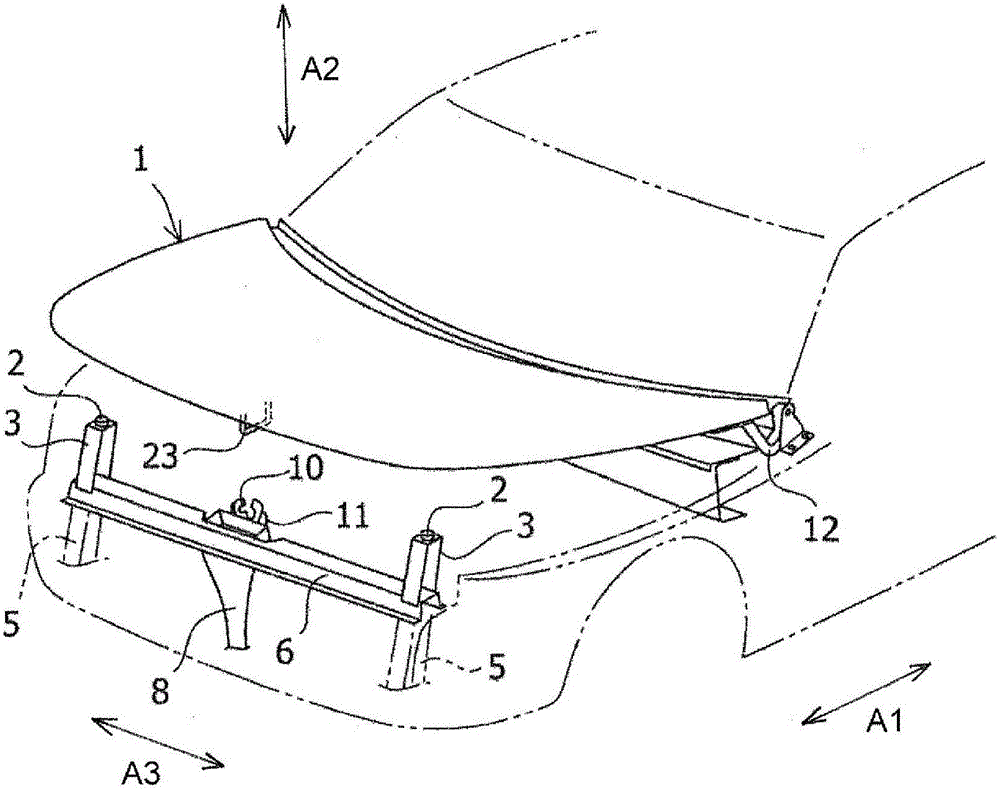
[0031] Below, use the attached drawings ( Figure 1 ~ Figure 5 ), an embodiment of the striker bracket attachment structure of the vehicle engine cover of the present invention will be described. figure 1 It is a brief representation of the vehicle front and rear direction of the vehicle having the striker bracket mounting structure of the vehicle hood of the present embodiment (in the figure 1 Is represented by arrow A1. ) Is a perspective view of the front part (front part of the vehicle). It should be noted that in figure 1 Here, the main body side of the vehicle body is imaginatively represented, and only the brief arrangement of the striker 23 is shown on the engine hood side, and the striker bracket 21 and the hood inner panel 20 are not shown.

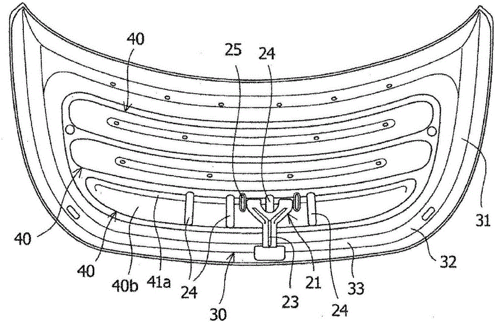
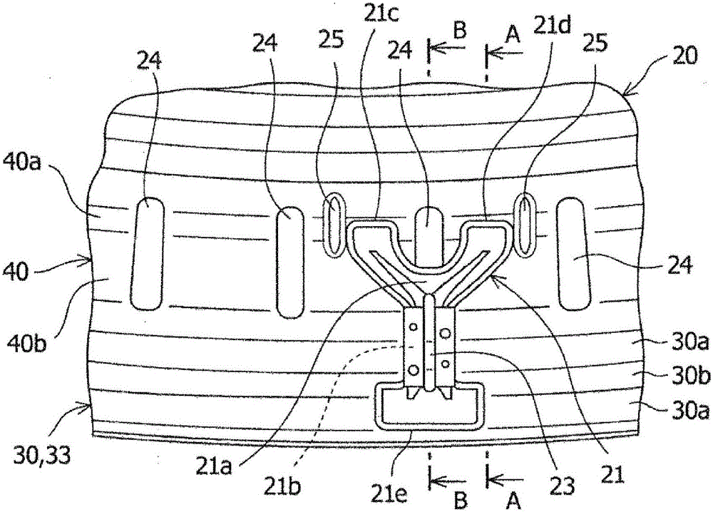
[0032] figure 2 Observed from under the vehicle figure 1 Bottom view of the inner side panel 20 of the hood. image 3 Is to figure 2 An enlarged bottom view showing the periphery of the striker bracket 21 enlarged. Figure 4 Yes ...


PUM


Abstract

A hood inner panel (20) to which a striker bracket (21) is attached is made of aluminum and is provided with an outer peripheral rib (30) and an inner rib (40). Slits (24) are formed in the inner rib (40) on the front side. The striker bracket (21) is branched on the rear side in a Y shape that opens toward the rear of the vehicle when viewed from below. The vehicle rear end parts (21c, 21d) of the striker bracket are connected to the inner rib (40) on respective sides of a single slit (24). The front end part (21e) of the striker bracket (21) is connected to the outer peripheral rib (30).

Description

Technical field [0001] The present invention relates to a striker bracket mounting structure for a vehicle hood in which the striker bracket is mounted on the inner panel of the hood. Background technique [0002] A vehicle hood such as a front hood panel covers the engine room from above the vehicle and is configured to be openable and closable. This engine hood has an engine hood outer panel constituting an outer panel and an engine hood inner panel constituting an inner panel (for example, Patent Document 1). [0003] The hood outer plate and the hood inner plate are usually formed of iron materials. In order to reduce the weight of vehicles, it is required to use raw materials that are lighter than iron materials. [0004] Prior technical literature [0005] Patent literature [0006] Patent Document 1: Japanese Patent Application Publication No. 2008-030574 [0007] The problem to be solved by the invention [0008] For example, in the case of forming the inner side panel of the h...

Claims


Application Information

Patent Timeline
IPC IPC(8): B62D25/10B62D25/12
CPCB62D29/008B62D25/105E05B83/24
Inventor 大石浩二山崎刚志永井克巳石飞秀树吉田正敏
Owner KOBE STEEL LTD
Why Eureka
Try Eureka