
water separator

A steam-water separator and hydrophobic technology, which is applied in separation methods, dispersed particle separation, chemical instruments and methods, etc., can solve the problem of low droplet separation size of demister net pad, inability to effectively separate small droplets, long-term supply of steam-water separator Improve the efficiency of equipment separation, simple structure and low cost

Active Publication Date: 2018-08-10
HANGZHOU ZHONGNENG STEAM TURBINE POWER CO LTD
View PDF7 Cites 2 Cited by
  • Summary
  • Abstract
  • Description
  • Claims
  • Application Information

AI Technical Summary

Problems solved by technology

[0003] The existing steam-water separator has problems such as complex structure, cumbersome manufacturing process, and long production cycle, which lead to a long supply cycle and high cost of the steam-water separator, which does not meet the current needs
On the other hand, today's manufacturing industry is fiercely competitive, and the supply cycle and price of products have been shortened again and again, which eventually leads to a decline in the profit of the steam separator.
[0004] In the principle of the steam-water separator, gravity settler, separation drum or demist net pad are commonly used. The former two devices have the problem of limited separation ability and cannot effectively separate fine droplets. Although the demist net pad has a small pressure drop and a The droplet separation size is low, but it is prone to clogging and other phenomena, which will affect the stable operation of the equipment

Method used


Image

  • water separator

Examples


Embodiment 1

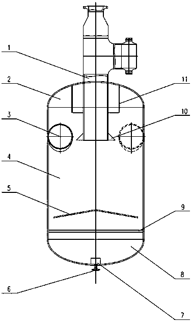
[0021] Such as figure 1 As shown, the steam-water separator described in this embodiment includes a steam exhaust pipe 1, an upper head 2, a steam inlet pipe 3, a cylinder body 4, a conical plate 5, a hydrophobic device 6, a vortex breaker 7, a lower seal Head 8, perforated plate 9, anti-liquid creep skirt 10 and cylindrical baffle 11.

[0022] The cylinder body 4 is welded with the upper head 2 and the lower head 8. There are two steam inlet pipes 3, which are installed on the upper part of the cylinder body 4 and arranged at an interval of 180°. Cut to set, and the steam inlet pipe 3 is inclined upward from the outside to the inside by 5°-15°, and the inclination angle is 10° as the best. Conical plate 5 and perforated plate 9 are installed on the lower part of cylinder body 4, steam exhaust pipe 1 and cylindrical baffle 11 are installed on the top of upper head 2, anti-liquid peristalsis skirt 10 is installed at the end of steam exhaust pipe 1, and lower head 8 Install hy...


PUM


Abstract

The invention discloses a steam-water separator. The steam-water separator comprises a barrel, an upper end enclosure, a lower end enclosure, an even number of steam inlet pipes and a steam outlet pipe. The steam inlet pipes are symmetrically arranged on the outer side of the upper portion of the barrel about the central axis of the barrel. The steam outlet pipe is arranged at the top of the upper end enclosure and stretches into the barrel, and a drainage device is arranged at the bottom of the lower end enclosure. A conical plate coaxial with the barrel is arranged on the lower portion of the barrel, the vertex of the conical plate is arranged upwards, a porous plate is arranged on the lower portion of the conical plate, the outer diameter of the conical plate is smaller than the inner diameter of the barrel, and the outer diameter of the porous plate is consistent with the inner diameter of the barrel. The steam-water separator of the structure has the advantages that the steam inlet pipes are used for steam inflow, so that steam forms a cyclone flow in the steam-water separator, and the steam-water separation effect is improved.

Description

technical field [0001] The invention relates to steam dehumidification and demisting equipment, in particular to a steam-water separator for a steam turbine. Background technique [0002] A steam turbine is a device that converts the thermal energy of steam into mechanical energy. During the working process of the steam turbine, the steam supplied needs to pass through the steam-water separator to ensure the dryness. If the effect of the steam-water separator is poor, the water in the steam will be too large, which will easily cause water hammer in the steam turbine, damage the blades, and even Cause serious accidents and affect the safe operation of the steam turbine. In the actual production process, there are not a few accidents caused by the insufficient efficiency of the steam-water separator. In order to prevent such accidents, the effect of the steam-water separator should be improved as much as possible to ensure the dryness of the steam inlet. [0003] The existi...

Claims


Application Information

Patent Timeline
Patent Type & Authority Patents(China)
IPC IPC(8): B01D45/16
CPCB01D45/16B04C5/04B04C5/103B04C5/13
Inventor 钱小东裘小裕王珂
Owner HANGZHOU ZHONGNENG STEAM TURBINE POWER CO LTD
Learn More