
Improved structure of shale shaker screen for offshore drilling

A technology for offshore drilling and screen mesh, which is applied in the direction of sieve, solid separation, grid, etc. It can solve the problems of loss and departure of the recoverable liquid phase of drilling fluid, and achieve the effect of protecting the environment, avoiding damage and reducing the cost of use.

Active Publication Date: 2018-06-12
广州智创知识产权运营有限公司
View PDF7 Cites 0 Cited by
  • Summary
  • Abstract
  • Description
  • Claims
  • Application Information

AI Technical Summary

Problems solved by technology

[0006] The technical problem to be solved by the present invention is aimed at the shortcomings of the screening mechanism of the traditional drilling fluid shale shaker. Phase particles and liquid phase leave the screen before they have time to separate, causing the problem of loss of recoverable liquid phase in drilling fluid

Method used


Image

  • Improved structure of shale shaker screen for offshore drilling

Examples


Embodiment

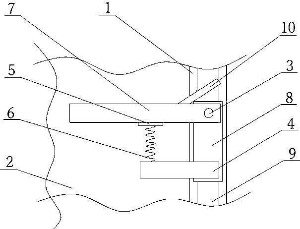
[0025] Such as figure 1 As shown, the present invention is an improved structure of a shale shaker screen used for offshore drilling, including a screen frame 1, a screen 2 is arranged in the screen frame 1, a guide rail 9 is arranged on the screen frame 1, and the guide rail 9 guides from the drilling The inlet of the drilling fluid extends to the outlet of the drilling fluid. A number of sliders 8 are arranged on the guide rail 9. A fixed baffle 4 is installed on the end of the slider 8 close to the outlet of the drilling fluid, and a movable baffle 7 is installed on the other end. The longer side of the contact surface between the baffle 4 and the slider 8 is perpendicular to the slider 8, the height of the fixed baffle 4 is parallel to the normal direction of the slider 8, the fixed baffle 4 is parallel to the movable baffle 7, and the fixed baffle 4 and the movable baffle 7 are provided with a spring 6, one end of the spring 6 is vertically fixed on the fixed baffle 4, an...


PUM


Abstract

The invention discloses an improved structure of screen cloth of a mud vibrating screen for marine drilling. The improved structure comprises a screen cloth frame, the screen cloth, a guide rail, a rail protection plate and sliding blocks, wherein a plurality of fixed baffles are arranged on the screen cloth frame; springs perpendicular to the fixed baffles are mounted on the side surfaces, facing to the inlet of the screen cloth, of the fixed baffles; the springs are connected with buffering pads; mobile baffles are parallel to the fixed baffles; rotating shafts parallel to the normal direction of the screen cloth frame are arranged at the positions, positioned on the screen cloth frame, of the mobile baffles; threads are formed on the side surfaces, close to the bottom ends, of the rotating shafts; the bottom ends of the rotating shafts penetrate through the mobile baffles and are inserted into screw holes formed in the screen cloth frame; the side surfaces of the mobile baffles are in contact with the buffering pads. According to the improved structure, a liquid phase and a solid phase in drilling fluid are further separated, to enhance the screening effect and avoid loss of the recyclable liquid phase due to the fact that the liquid phase in the drilling fluid moves to an outlet of the screen cloth along with the solid phase without being separated from the solid phase during screening; therefore, the use cost of the drilling fluid is reduced, and the environment is protected.

Description

technical field [0001] The invention relates to the field of drilling fluid recovery, in particular to an improved structure of a shale shaker mesh used for offshore drilling. Background technique [0002] Drilling fluid is a general term for various circulating fluids used in the drilling process, and drilling fluid is also called drilling mud. During the drilling process, the drilling fluid can effectively cool and lubricate the drill bit, and can also balance the underlying pressure to avoid blowout and kick. In addition, the drilling fluid can also transmit power and take coring samples. According to different dispersion media, drilling fluids are mainly divided into three categories: water-based drilling fluids, oil-based drilling fluids and gas-based drilling fluids. [0003] During the drilling process, the drilling fluid enters the bottom layer through the drill pipe, and after completing its function, it is discharged together with the slag generated in the drillin...

Claims


Application Information

Patent Timeline
Patent Type & Authority Patents(China)
IPC IPC(8): B07B1/46B07B1/28
CPCB07B1/28B07B1/46
Inventor 谭正怀
Owner 广州智创知识产权运营有限公司
Learn More