
A Parallel Supporting Robot for Indoor Architecture with Angle Adjustment Function

An angle adjustment and robot technology, applied in the direction of manipulators, manufacturing tools, program control manipulators, etc., can solve the problems of poor equipment stability, non-adjustable fixed angle, poor height adjustment performance, etc.

Active Publication Date: 2017-11-07
浙江爱尚家科技股份有限公司
View PDF6 Cites 0 Cited by
  • Summary
  • Abstract
  • Description
  • Claims
  • Application Information

AI Technical Summary

Problems solved by technology

[0003] In order to solve the above problems, the present invention provides an indoor building parallel support robot with an angle adjustment function, which can solve the problems of poor rigid support performance, poor equipment stability, and poor shock absorption performance of existing cleaning height auxiliary equipment. The fixed angle cannot be adjusted, the rotation angle cannot be adjusted, the height adjustment performance is poor, the scope of application is small, and the work efficiency is low. It can realize the stable rigid support function when the indoor building is cleaned. It has good rigid support performance, good equipment stability, and equipment. Good shock absorption performance, adjustable fixed angle, adjustable rotation angle, good height adjustment performance, wide application range and high work efficiency, etc.

Method used


Image

  • A Parallel Supporting Robot for Indoor Architecture with Angle Adjustment Function
  • A Parallel Supporting Robot for Indoor Architecture with Angle Adjustment Function
  • A Parallel Supporting Robot for Indoor Architecture with Angle Adjustment Function

Examples


Embodiment Construction

[0028] In order to make it easy to understand the technical means, creation features, achieved goals and effects of the present invention, the present invention will be further described below with reference to the specific figures.

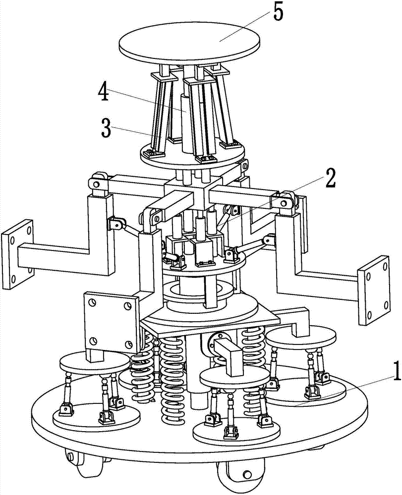
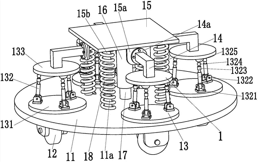
[0029] like Figure 1 to Figure 12 As shown, an indoor building parallel support robot with an angle adjustment function includes a self-stable support device 1, and the self-stable support device 1 has good rigid support performance, stability performance and shock absorption performance. A locking adjustment device 2 is installed in the middle of the end face. The fixed angle and rotation angle of the locking adjustment device 2 can be adjusted. The upper end surface of the locking adjustment device 2 is symmetrically installed with four rigid lifting branches 3. The rigid lifting branch 3 has Good height lifting adjustment performance, the middle of the upper end face of the locking adjustment device 2 is installed with the No. 4 hydraulic cyl...


PUM


Abstract

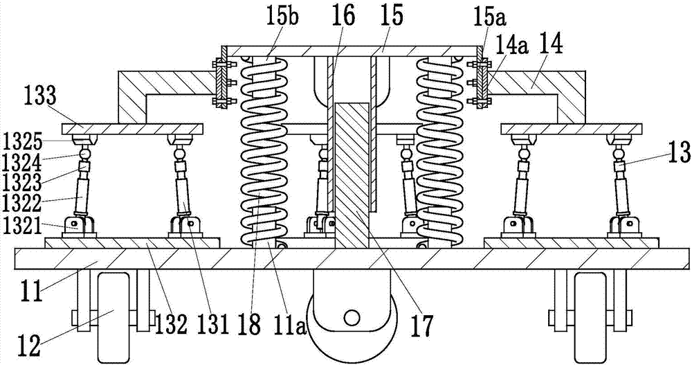
The invention relates to an indoor building parallel supporting robot with an angle adjustment function. The indoor building parallel supporting robot with the angle adjustment function comprises a self-stabilizing supporting device. The self-stabilizing supporting device has good rigid supporting performance, stability and damping performance. A locking adjustment device is installed on the middle portion of the upper end face of the self-stabilizing supporting device. The fixing angle and rotating angle of the locking adjustment device can be adjusted. Four rigid lifting branched chains are symmetrically installed on the upper end face of the locking adjustment device through screws. The rigid lifting branched chains have good height lifting adjustment performance. A fourth hydraulic cylinder is installed on the middle portion of the upper end face of the locking adjustment device. A circular truncated cone is installed at the top ends of the four rigid lifting branched chains and the top end of the fourth hydraulic cylinder. The self-stabilizing supporting device comprises a fixed circular truncated cone. Four parallel supporting branched chains are evenly installed on the upper end face of the fixed circular truncated cone in the axis direction. Four L-shaped supporting columns are symmetrically installed on the middle portions of the upper end faces of the four parallel supporting branched chains. By the adoption of the indoor building parallel supporting robot with the angle adjustment function, a stable rigid supporting function can be achieved during cleaning of an indoor building.

Description

technical field [0001] The invention relates to the field of building environmental protection equipment, in particular to an indoor building parallel support robot with an angle adjustment function. Background technique [0002] With the continuous development of social economy, all kinds of high-rise buildings are rising. However, with the continuous growth of the number of high-rise buildings, more and more cleaning workers maintain the environmental sanitation of high-rise buildings. The cleaning scope includes floors, glass windows, walls, etc. Ceramic tiles, suspended ceilings or ceilings, etc. Although there are many cleaning robots on the market, they only have the function of automatically cleaning the bottom plate and glass windows. Indoor wall tiles, suspended ceilings or ceilings still need to be manually processed on a regular basis. No automated cleaning equipment has been developed yet. When the height of the tiles, suspended ceilings and ceilings is high, a h...

Claims


Application Information

Patent Timeline
Patent Type & Authority Patents(China)
IPC IPC(8): B25J9/00
CPCB25J9/0045
Inventor 朱新科
Owner 浙江爱尚家科技股份有限公司
Learn More