

Manipulator component of a general robot
A manipulator component and robot technology, applied in the field of robotics, can solve problems such as workpiece falling off, multiple claws moving in the same range, and grasping the workpiece.
- Summary
- Abstract
- Description
- Claims
- Application Information
AI Technical Summary
Problems solved by technology
Method used
Image

Examples
Embodiment Construction
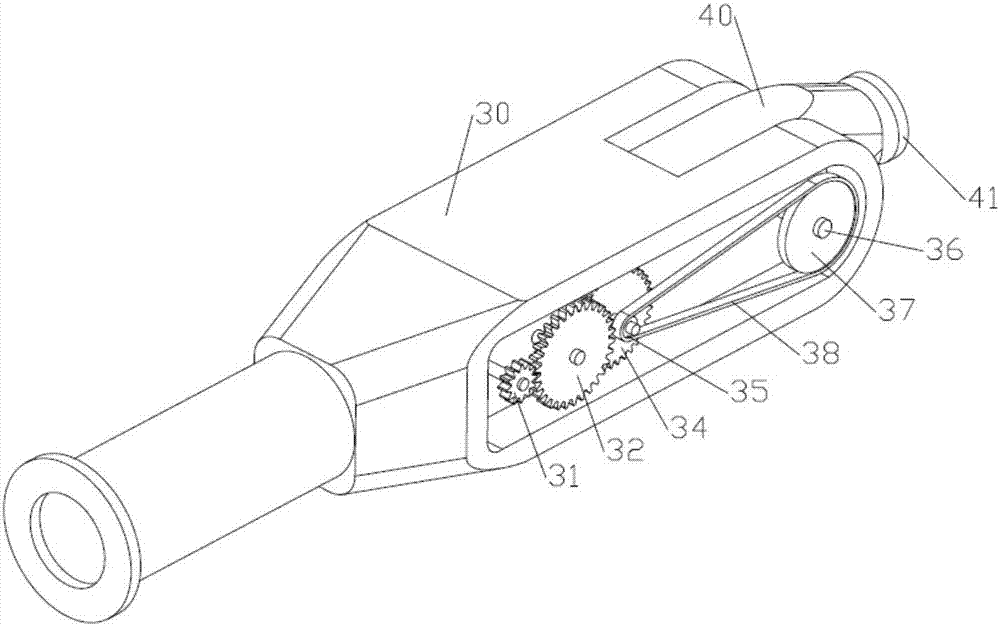
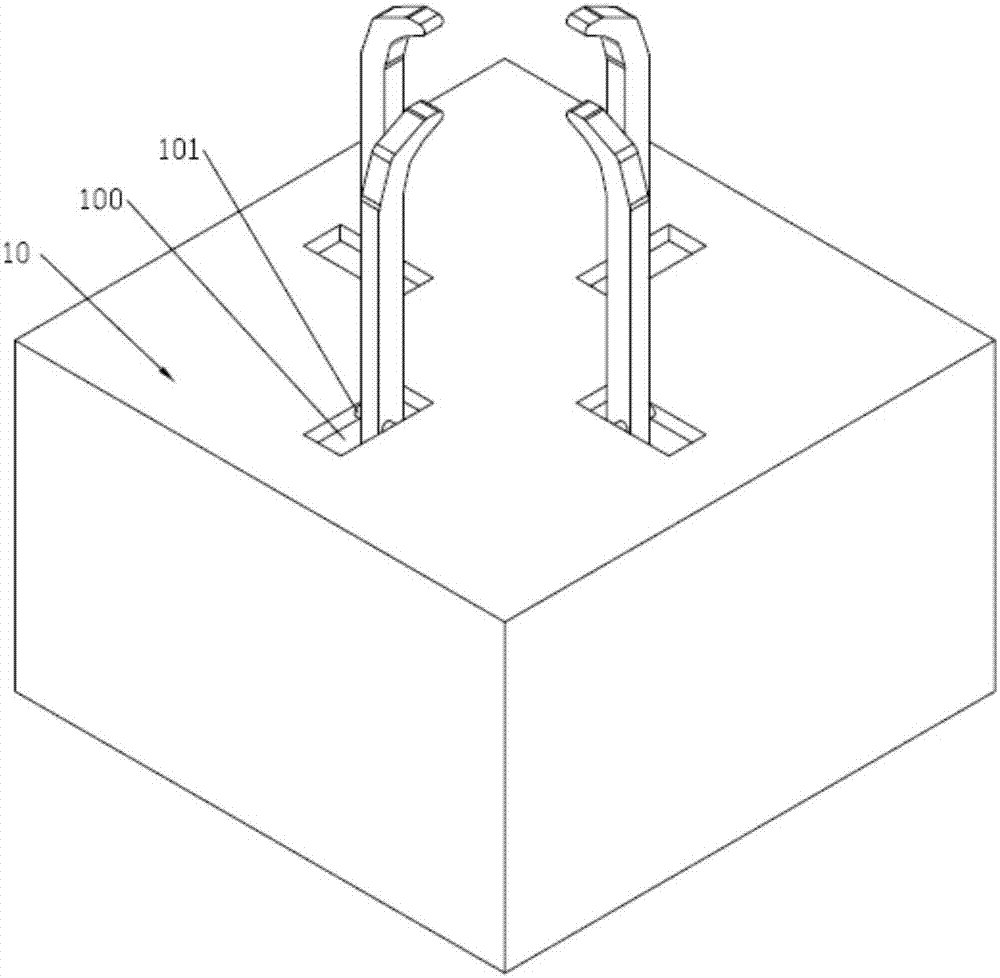
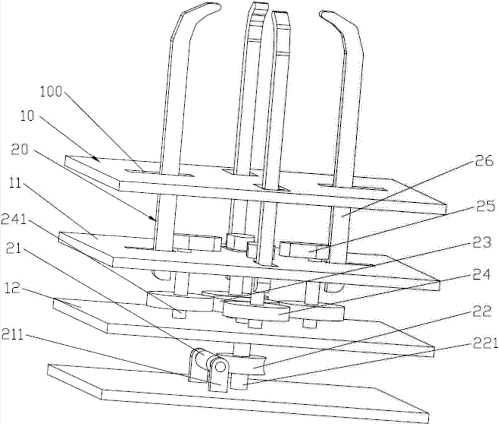
[0023] like Figure 1 to Figure 8 As shown, a manipulator assembly of a general robot includes an arm 30, a swing arm 40 pivotally connected to the front end of the arm 30, a first drive unit for driving the swing arm 40 to swing, a manipulator fixed on the rotating disc 41 at the front end of the swing arm 40, and The second drive unit that drives the rotating disk 41 to rotate; the centerline of the swing arm 40 when swinging is perpendicular to the rotation centerline of the rotating disk 41; the manipulator includes a housing 10 and a gripper drive mechanism 20; Drive motor 27, worm screw 21, worm wheel 22, central gear 23, some sub-gears 24, some cams 25 and some grippers 26;
[0024] like Figure 1 to Figure 8 As shown, the housing 10 is a cuboid with a cavity inside; the gripper driving mechanism 20 is arranged in the inner cavity of the housing 10; the center of the housing 10 is formed with a first support plate 11 and a second support plate arranged horizontally and...
PUM
 Abstract
Description
Claims
Application Information