Sliding foot assembly and movable mold plate supporting structure using same

A supporting structure and moving template technology, which is applied in the field of pressure forming equipment, can solve the problems of slow mold moving acceleration, large frictional resistance, failure of linear guide rolling elements, etc., and achieve the effect of reducing demand and improving service life

Active Publication Date: 2016-08-24
BORCH MACHINERY
View PDF3 Cites 3 Cited by
  • Summary
  • Abstract
  • Description
  • Claims
  • Application Information

AI Technical Summary

Problems solved by technology

[0002] At present, the clamping mechanism of injection molding machine and die-casting molding machine mainly uses sliding fit between the movable platen and the frame when moving the mold, and uses pull rods to slide and fit guide supports. Multiple sliding fit guide supports will produce various unstable frictional resistances. The speed of the mold moving process is unstable, the frictional resistance is large, and the acceleration of the mold moving is slow, resulting in a long mold moving cycle and low machine production efficiency. The moving template and the frame are supported by linear guide rails, which is a more advanced technology at present.
[0003] During the mold locking process, the clamping force will act on the movable template to cau

Method used


Image

  • Sliding foot assembly and movable mold plate supporting structure using same
  • Sliding foot assembly and movable mold plate supporting structure using same
  • Sliding foot assembly and movable mold plate supporting structure using same

Examples


Example Embodiment

[0038] The technical solutions of the present invention will be further described below in conjunction with the accompanying drawings and through specific implementation methods.

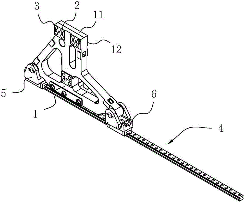
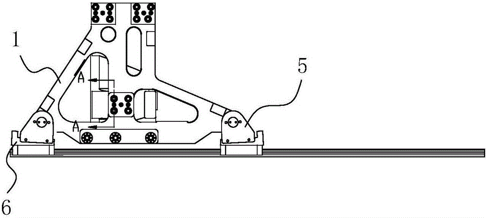
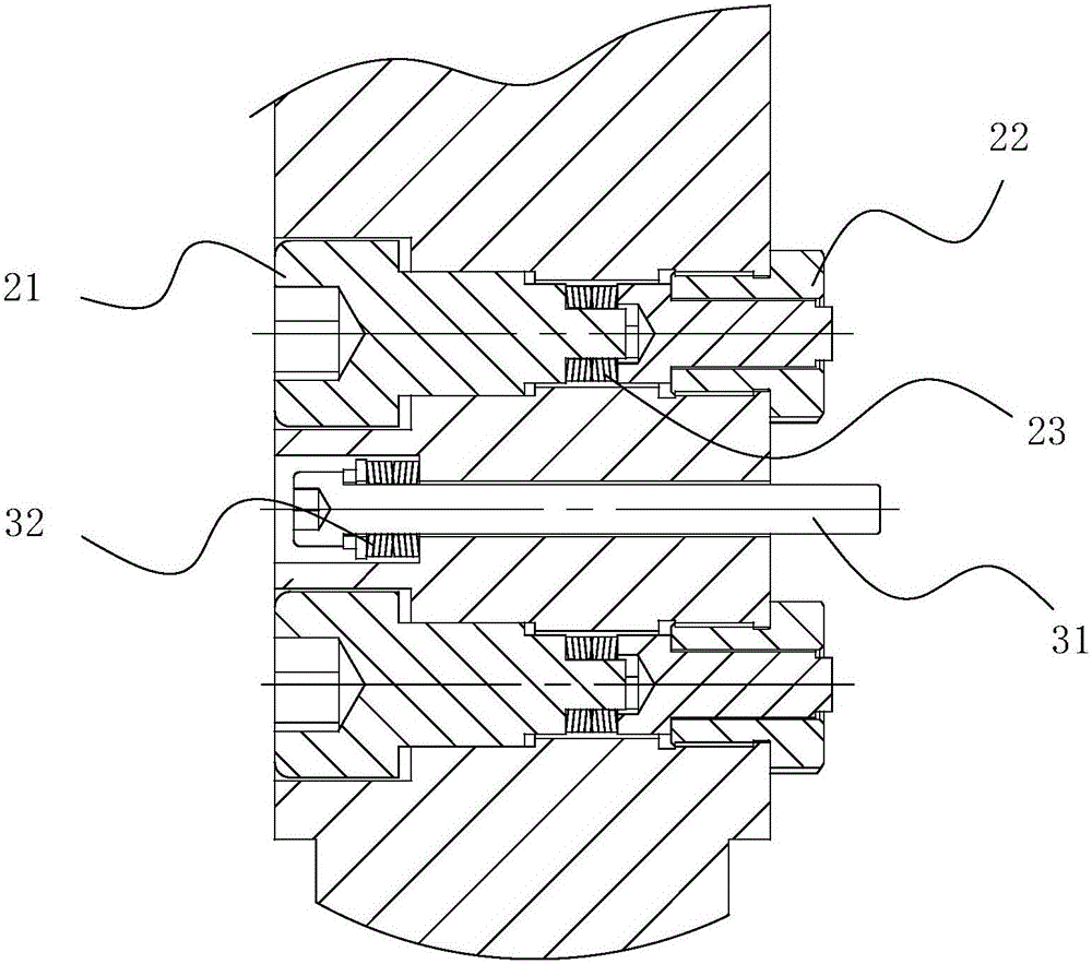
[0039] like Figure 1-7 As shown, in this embodiment, a slider assembly according to the present invention includes a slider body 1 having a first support end surface 11 and a second support end surface 12 perpendicular to each other, and the slider body 1 is provided with There is an elastic support assembly 2 for directly supporting the supported object in contact with the supported object, one end of the elastic support assembly 2 protrudes from the surface of the second support end surface 12, and the elastic support assembly 2 The other end is fixedly connected with the slider main body 1 .

[0040] In this embodiment, the first support end surface 11 is a horizontal support surface for bearing the force of the supported part on the slider body 1 in the direction of gravity, and the second sup...


PUM


Abstract

The invention discloses a sliding foot assembly. The sliding foot assembly comprises sliding foot bodies, wherein each sliding foot body is provided with a first supporting end face and a second supporting end face perpendicular to each other. The sliding foot bodies are provided with elastic supporting assemblies which make contact with supported pieces and are used for supporting the supported pieces directly. One end of each elastic supporting assembly protrudes out of the surface of the corresponding second supporting end face, and the other end of each elastic supporting assembly is fixedly connected with the corresponding sliding foot assembly. The invention further discloses a movable mold plate supporting structure using the sliding foot assembly. Due to the arrangement of the elastic supporting assemblies, the mold locking deformation force transmitted to linear guide rails is greatly lowered, an ultra-large type machine can also be designed to be in linear guide rail guiding supporting, and the ultra-large type machine can achieve high-speed, high-efficiency and stable control production.

Description

technical field [0001] The invention relates to the technical field of pressure forming equipment, in particular to a movement support structure of a clamping mechanism of an injection molding machine and a die-casting molding machine, in particular to a sliding foot assembly and a moving template support structure using the same. Background technique [0002] At present, the clamping mechanism of injection molding machine and die-casting molding machine mainly uses sliding fit between the movable platen and the frame when moving the mold, and uses pull rods to slide and fit guide supports. Multiple sliding fit guide supports will produce various unstable frictional resistances. It leads to unstable speed of mold moving process, high frictional resistance, slow mold moving acceleration, long mold moving cycle and low machine production efficiency. It is currently more advanced technology to use linear guide rail rolling guide support for moving template and frame. [0003] D...

Claims


Application Information

Patent Timeline
IPC IPC(8): B29C45/66B22D17/26
CPCB22D17/263B29C45/66
Inventor 叶廷璧
Owner BORCH MACHINERY
Why Eureka
Try Eureka