Eureka AIR delivers breakthrough ideas for toughest innovation challenges, trusted by R&D personnel around the world.

Oil-accumulating oil-absorbing vessel

An oil-absorbing ship and oil-gathering technology, which is applied in the direction of hull, shipbuilding, hull design, etc., can solve the problems of damaging the water environment, not being environmentally friendly, and not being able to adapt to thin-layer oil slicks, etc., to achieve high treatment efficiency, high oil absorption efficiency, and increased The effect of oil residence time

Inactive Publication Date: 2019-01-22
WUHAN UNIV OF TECH
View PDF4 Cites 0 Cited by
  • Summary
  • Abstract
  • Description
  • Claims
  • Application Information

AI Technical Summary

Problems solved by technology

[0002] At present, the following two methods are traditionally used to deal with oil spills on water: 1) Prevent the spread of dirty oil through oil containment booms, and recover the floating oil through mechanical transmission through conveyor belts. This method requires the deployment of large-scale machinery, which is heavy and unsuitable for operation. , the conveyor belt can only recover oil spills within the distribution range and located in the thick oil slick area; 2) burn the slick oil, and use microorganisms to decompose the oil or use chemical methods to treat the oil, which will damage the water environment and will not Environmental friendly
Therefore, it is an efficient and environmentally friendly way to use oil suction ships for mobile oil absorption treatment. However, the existing oil suction ships have a small treatment range and use oil pumping methods, which cannot adapt to thin oil slicks.

Method used


Image

  • Oil-accumulating oil-absorbing vessel
  • Oil-accumulating oil-absorbing vessel
  • Oil-accumulating oil-absorbing vessel

Examples


Embodiment Construction

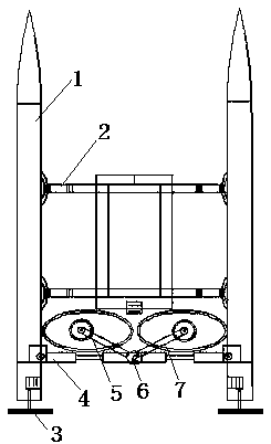
[0033] The present invention will be further described below in conjunction with the accompanying drawings and embodiments.

[0034] like figure 1 Shown, a kind of oil-gathering type oil-absorbing ship comprises hull and is located on the oil-absorbing device 7 on hull, as Figure 5 As shown, the oil suction device 7 includes an oil suction cover 12 with the opening facing downwards. The bottom edge of the oil suction cover 12 can generate negative pressure. motor 14) and suction nozzle 17 (the suction nozzle 17 is connected to the oil storage mechanism through the suction pipe 16 through the oil suction cover 12, and the suction pipe 16 is set near the rotating shaft 15), the suction nozzle 17 inlet is downward and is located on the spiral blade 26 ( Three groups of suction nozzles 17 and suction pipes 16 are arranged above the rotating blade 18). During operation, the bottom of the oil suction cover 12 is higher than the liquid surface, the inlet of the suction nozzle 17 is...


PUM


Abstract

The invention relates to an oil gathering type oil sucking ship which comprises a ship body and oil sucking devices arranged on the ship body. Each oil sucking device comprises an oil sucking hood with an opening facing downwards. Negative pressure can be generated on the edges of the bottoms of the oil sucking hoods. Spiral blades and a suction nozzle are arranged in a center area in each oil sucking hood. An inlet of each suction nozzle faces downwards and is located above the corresponding spiral blades. During work, the bottoms of the oil sucking hoods are higher than a liquid level, the inlets of the suction nozzles are attached to the liquid level, and the spiral blades are lower than the liquid level. The oil sucking ship firstly collects floating oil in a treating area, then forms a thick oil layer in a centralized manner, and finally extracts away the thick oil layer in a centralized manner; and the treating efficiency is high, and the oil gathering type oil sucking ship is suitable for treating thin-layer floating oil and floating oil distributed in a large range.

Description

technical field [0001] The invention belongs to the field of oil spill treatment, and in particular relates to an oil gathering type oil suction ship. Background technique [0002] At present, the following two methods are traditionally used to deal with oil spills on water: 1) Prevent the spread of dirty oil through oil containment booms, and recover the floating oil through mechanical transmission through conveyor belts. This method requires the deployment of large-scale machinery, which is heavy and unsuitable for operation. , the conveyor belt can only recover oil spills within the distribution range and located in the thick oil slick area; 2) burn the slick oil, and use microorganisms to decompose the oil or use chemical methods to treat the oil, which will damage the water environment and will not Environmental friendly. Therefore, it is an efficient and environmentally friendly way to use oil suction ships for mobile oil suction treatment. However, the existing oil s...

Claims


Application Information

Patent Timeline
Patent Type & Authority Patents(China)
IPC IPC(8): E02B15/10B63B35/32B63B1/32
CPCB63B1/32B63B35/32E02B15/10E02B15/107Y02A20/204Y02T70/10
Inventor 乐京霞罗五雄申浩
Owner WUHAN UNIV OF TECH
Why Eureka
Eureka Blog
Learn More