
Straining beam cable rod dome structure and construction method thereof

A construction method and technology of pulling beams and cables, applied to the structure of the dome, arch structure, building components, etc., can solve the problems of difficult laying of rigid roof materials and difficult construction, and achieve easy laying of rigid roofs, small deflection, The effect of small pretension

Inactive Publication Date: 2016-08-24
SOUTHEAST UNIV
View PDF7 Cites 15 Cited by
  • Summary
  • Abstract
  • Description
  • Claims
  • Application Information

AI Technical Summary

Problems solved by technology

[0004] Purpose of the invention: The purpose of the present invention is to solve the problem that it is difficult to lay rigid roofing materials for cable domes, and it is easy to lay rigid roofing materials for suspension domes because of the upper reticulated shell, but the construction is difficult, and to provide a tension beam cable-strut dome structure and its construction method

Method used


Image

  • Straining beam cable rod dome structure and construction method thereof
  • Straining beam cable rod dome structure and construction method thereof
  • Straining beam cable rod dome structure and construction method thereof

Examples


Embodiment

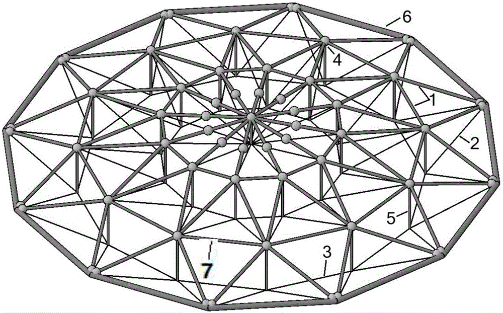
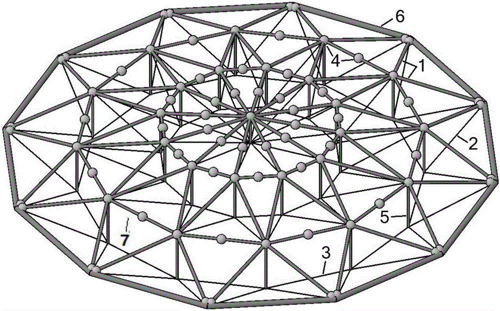
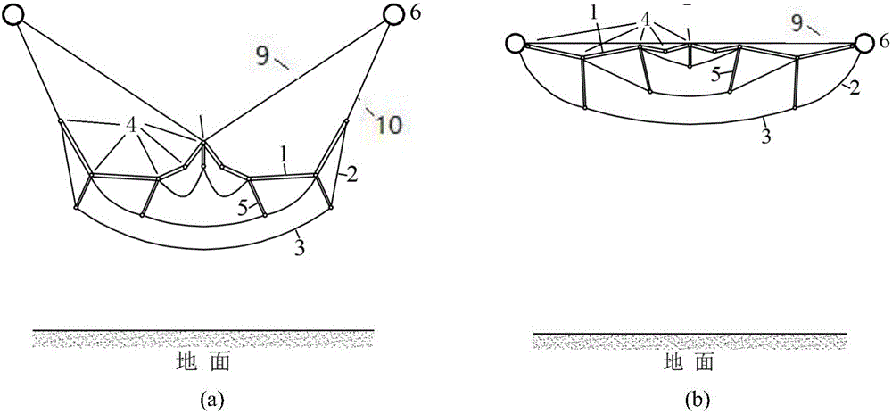
[0053] A tension beam cable-strut dome structure of the present invention comprises a radial tension beam 1, a circumferential tension beam 7, an oblique cable 2, a pressure rod 5, a hoop cable 3, an outer pressure ring 6 and a tension beam hinge 4. The beam 1 and the hoop tension beam 7 form triangular units of different shapes and sizes. The triangular units are connected to each other and share one side to form a tension beam grid. A compression bar 5 extends downward from the connection of the triangular units. In particular, the central compression bar 5 It can also be replaced by an inner pull ring. The slant cable 2 connects the lower end of the pressure rod 5 on the inner side of each adjacent two rings and the upper end of the pressure rod 5 on the nearest outer side, or the lower end of the outermost ring pressure rod 5 and the outer pressure ring 6, and the ring rope 3 is connected. The lower end of the compression rod 5 of the same ring, the tension beam hinge 4 is ...


PUM


Abstract

The invention discloses a straining beam cable rod dome structure and a construction method of the straining beam cable rod dome structure. The straining beam cable rod dome structure comprises radial straining beams, circumferential straining beams, stay cables, pressing rods, annular cables, outer pressing rings and staining beam hinges, wherein different shapes and different sizes of triangular units are formed by the radial straining beams and the circumferential straining beams; the triangular units are connected to each other and share one edge to form a straining beam grid; connecting positions of the triangular units stretch downwards to form the pressing rods; each stay cable is connected with the lower ends of the pressing rods arranged at the inner sides of every two adjacent rings and the upper end of the pressing rod arranged at the outer side nearest to the stay cable, or is connected with the lower end of the pressing rod arranged at the outmost ring and the outer pressing rings; the annular cables are connected with the lower ends of the pressing rods in the same ring; the straining beam hinges are arranged at the end parts or the middle parts of the radial straining beams and the circumferential straining beams in the straining beam grid; the straining beam grid, the outer pressing rings, the pressing rods and the stay cables are mutually hinged. The invention also provides the construction method for low-altitude assembly and high-altitude tension forming. The invention provides a space tension structure for paving rigid roof materials, and construction is carried out by adopting an integrated pulling and lifting mechanism expansion method.

Description

technical field [0001] The invention discloses a novel tension structure composed of tension beam grids, stay cables and hinged outer pressure rings, belongs to the technical field of civil engineering space structures, and specifically relates to a dome structure and a construction method thereof. Background technique [0002] As one of the main structural types of space structures, cable structures have been widely used in building structures at home and abroad. At present, the commonly used cable structure forms in engineering include string beams, suspension domes, cable-stayed grids, cable domes, and cable trusses. , cable net, etc. Among them, the cable dome based on the idea of ​​tensegrity, with its novel structural shape and ingenious conception, has attracted the favor of architects and structural engineers once it came out. The conventional cable dome is a kind of notochord. The flexible space tension structure composed of ring cables, pressure rods and external p...

Claims


Application Information

Patent Timeline
Patent Type & Authority Applications(China)
IPC IPC(8): E04B1/32
CPCE04B1/3211E04B2001/3223E04B2001/3229E04B2001/3294
Inventor 罗斌丁明珉潘杰郭正兴
Owner SOUTHEAST UNIV
Learn More