Prefabricated Truss-Embedded Composite Beam

一种组合桁架、组合梁的技术,应用在组合梁领域,能够解决截面硬性弱、钢板单元火灾弱、难以期待现场施工操作性或节约工期等问题,达到韧性强、宽操作空间、节约搬运及保管费用的效果

Inactive Publication Date: 2016-08-24
权容觐
View PDF6 Cites 15 Cited by
  • Summary
  • Abstract
  • Description
  • Claims
  • Application Information

AI Technical Summary

Problems solved by technology

The steel plate assembly composite beam proposed in this patent is combined with the web on the side of the lower cam, and there is no part protruding toward the side of the web, so that the part where dust accumulates on the structure itself can be removed in principle, but it is formed as a permanent mold function. The "U"-shaped steel plate unit is usually composed of a thin plate with a thickness of about 6mm, so the section rigidity is very weak and it is difficult to support the construction load generated when the steel plate unit is filled with concrete and when the bottom plate is assembled with steel bars and poured with concrete. Therefore, In the construction process, a support is placed in the middle of the steel plate unit for construction, so it is difficult to expect on-site construction operability or saving time, and the exposed steel plate unit is very weak to fire

Method used


Image

  • Prefabricated Truss-Embedded Composite Beam
  • Prefabricated Truss-Embedded Composite Beam
  • Prefabricated Truss-Embedded Composite Beam

Examples


Embodiment Construction

[0035] Hereinafter, the present invention will be described in detail with reference to the embodiments shown in the drawings. However, the shown embodiments are only illustrative for the convenience of understanding the present invention, and are not intended to limit the present invention.

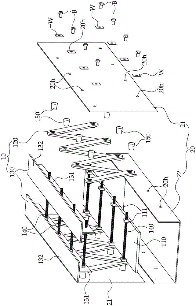
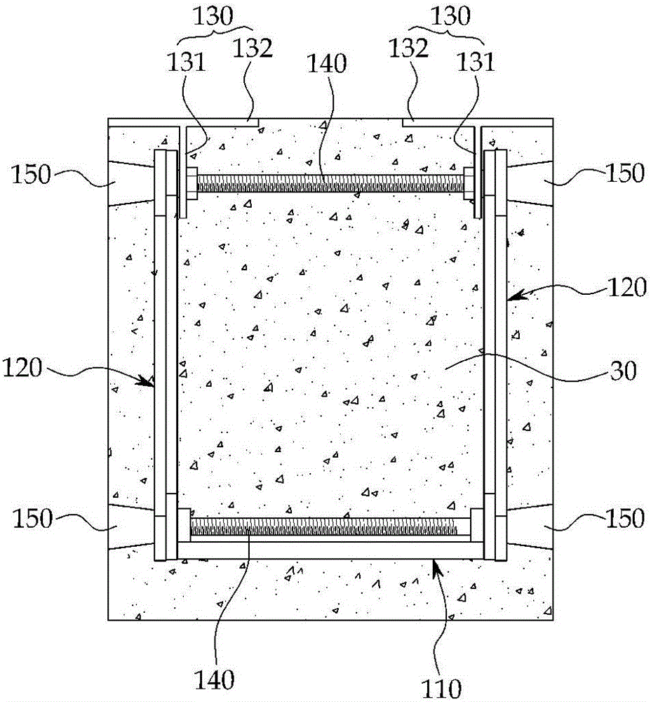
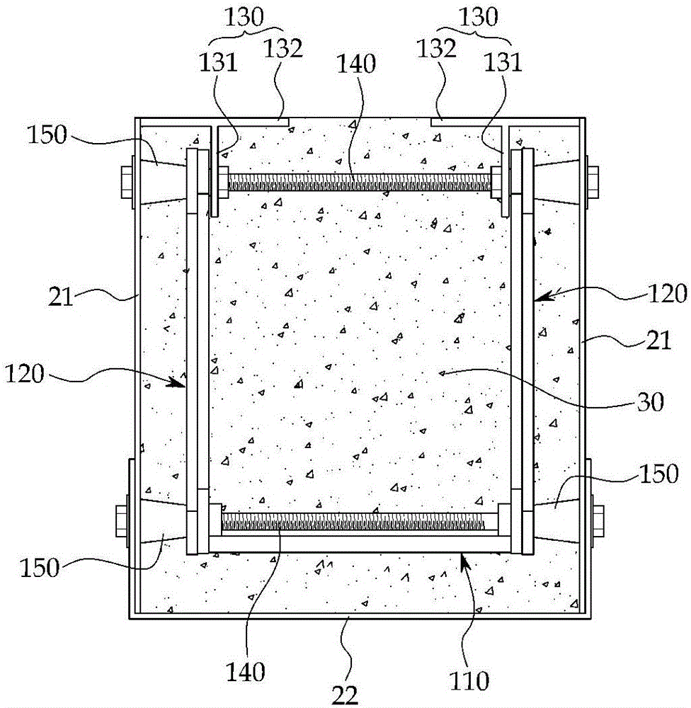
[0036] figure 1 It is an exploded perspective view of a composite truss embedded composite beam with a formwork attached according to an embodiment of the present invention, Figure 2a and 2b is a cross-sectional view.

[0037] The composite truss-embedded composite beam with formwork attached according to the present invention roughly includes a composite truss 10 , a formwork 20 and concrete 30 .

[0038]The composite truss 10 is composed of truss components including a lower suspension material, a composite material, and an upper suspension material. The lower suspension material 110 of the composite truss 10 according to the present invention is formed into a plate shape with a spe...


PUM


Abstract

The invention provides a prefabricated truss-embedded composite beam. The beam with a sheathing board comprises: a combined truss. The truss comprises: a lower chord which is configured in a plate shape with a fixed thickness; a pair of foldable web members which are configured in a zigzag shape by connecting ends of multiple flat steel bars, and have lower ends coupled to both ends of the width direction of the lower chord after the screw rods coupled to the lower chord penetrate through holes formed on joints of the flat steel bars and D-cones are externally coupled; a pair of upper chords which are configured so as to comprise a vertical plate having coupling holes perforated therein at certain intervals along the longitudinal direction, and a horizontal plate configured on the upper end of the vertical plate, and which are coupled to the pair of foldable web members after the screw rods penetrate the coupling holes of the vertical plate and the upper through holes of the foldable web member and the D-cones are externally coupled; the sheathing board which is configured so as to accommodate the combined truss within the cross section thereof and to have a U-shaped cross section with an opened upper surface, and is fixed to the combined truss after bolt holes are perforated at positions corresponding to the D-cones coupled to the upper chord and the lower chord of the prefabricated truss and bolts are externally coupled to the D-cones through the bolt holes; and concrete which is integrated with the prefabricated truss by being placed within the cross section of the sheathing board. The sheathing board is removed by loosening the bolts after the concrete is cured.

Description

technical field [0001] The present invention relates to a composite beam for embedding a composite truss in concrete. More specifically, it relates to a composite truss that plays the role of a truss beam supporting the self-weight of the concrete and the construction load in the liquid state before the concrete is hardened. After the concrete hardens Composite beams that act together with concrete as the primary structural member. Background technique [0002] Reinforced concrete structures require formwork to maintain the shape of liquid concrete during concrete curing, and ordinary joists, brackets, and pillars are required to provide structural safety and prevent sagging during construction. Therefore, the reinforced concrete structure is accompanied by additional steps such as removing the formwork and removing the pillars, so the construction is complicated and the construction period is long. [0003] Although the steel structure does not require other temporary inst...

Claims


Application Information

Patent Timeline
Patent Type & Authority Applications(China)
IPC IPC(8): E04C3/293E04C5/065
CPCE04C3/293E04C5/065E04B5/40E04C3/005E01D2101/262E04B2001/2448E04B2001/2457E04B2001/4192E04C3/205E04C3/291
Inventor 权容觐
Owner 权容觐
Why Eureka
Try Eureka