Automobile cable detection machine
A cable detection machine and automobile technology, which is applied in the direction of vehicle testing, measuring devices, testing of mechanical parts, etc., to achieve high-precision automatic detection and reliable technical indicators
- Summary
- Abstract
- Description
- Claims
- Application Information
AI Technical Summary
Problems solved by technology
Method used
Image
Examples
Embodiment 1
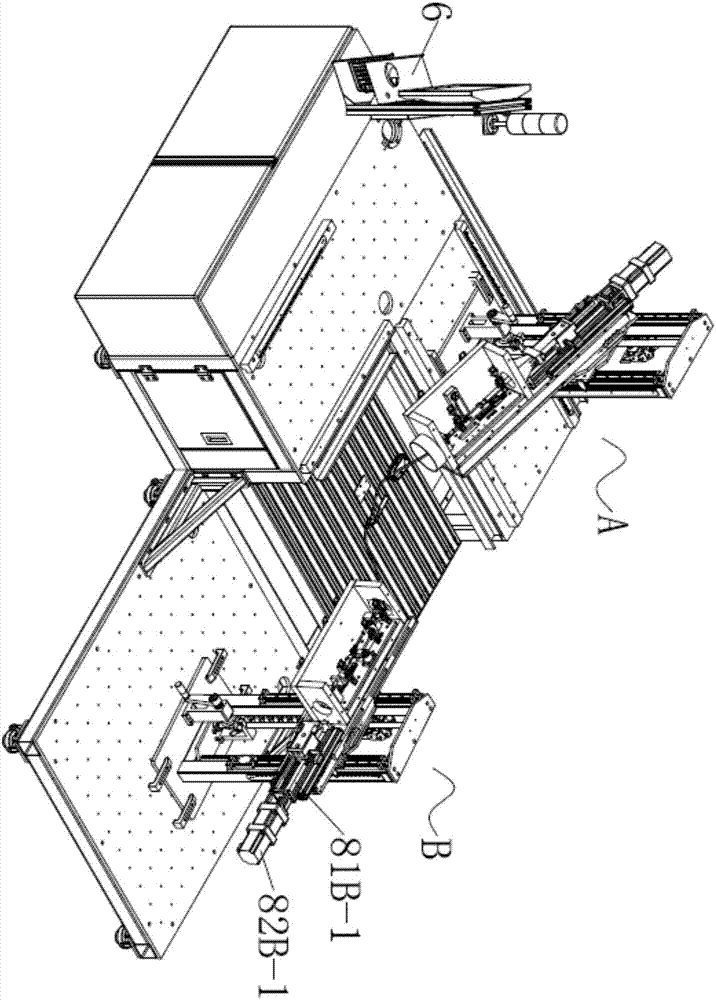
[0050] Such as figure 1 , 5 , 11, the present embodiment discloses a vehicle cable detection machine, the drive end simulation assembly A, the load end simulation assembly B, the controller 6, the drive end simulation assembly A fully simulates the actual operation of the vehicle when pulling The action environment of the driving end of the cable, the simulation assembly B of the load end completely simulates the action environment of the load end of the cable when the vehicle is actually operated.
[0051] Specifically, the driving end simulation assembly A: it includes a first installation platform 2A, a gear shift simulator 4A fixed on the first installation platform 2A, and a driving end for the vehicle cable 1 The driving end driving assembly 8A that provides the power source, the driving end of the automobile cable 1 is fixed on the driving end driving assembly 8A after passing through the shift simulator 4A, and the driving end driving assembly 8A includes a driving sc...
Embodiment 2
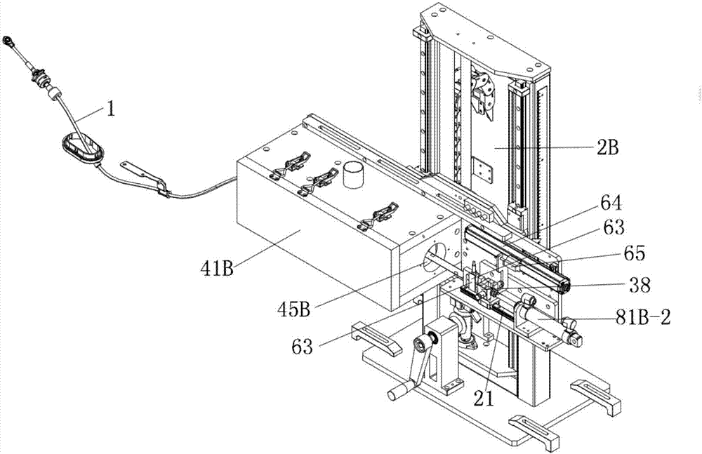
[0062] Such as figure 2 As shown, the difference between Embodiment 2 and Embodiment 1 is only that the load driver 8B forming the analog assembly B at the load end is different. The load driver 8B in this embodiment is a cylinder drive assembly, and the cylinder drive assembly includes a drive cylinder 81B-2, the cylinder barrel of the driving cylinder 81B-2 is fixed on the second installation machine 2B, and its piston rod is connected to the connecting seat 38.
[0063] In this implementation, when testing the ⑦ (displacement efficiency) of the automobile cable 1, the test mode is the displacement mode operation: the load end of the automobile cable 1 passes through the connecting block 44 and passes through the first sealed box 41A and the second force The sensor 63 is connected, and the load driver 8 formed by the cylinder drive assembly is cut into use. The test process is as follows: when the driving end pulls the vehicle cable 1, the load driver 8 pulls the vehicle c...
Embodiment 3
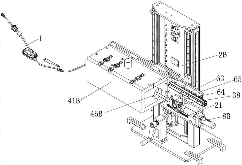
[0065] Such as image 3 , 6 , 7, the difference between this embodiment and the first embodiment is only that the load driver 8B forming the load end analog assembly B is different. In this embodiment, the load driver 8B is a shaft sleeve drive assembly, and its specific structure is as follows: The shaft sleeve driving assembly includes a shaft sleeve 82 and a moving shaft 81 which is penetrated in the shaft sleeve 82 and can move axially. The shaft sleeve 82 and the moving shaft 81 are arranged coaxially, and the moving shaft 81 passes One end of the sleeve is fixed on the connecting seat 38; wherein, the moving shaft 81 includes a first straight line segment 811, a second straight line segment 812 and a third straight line segment 813 which are sequentially connected and arranged coaxially. The shaft diameter of the second straight section 812 is greater than the shaft diameter of the first straight section 811, so that the second straight section 812 is connected to the f...
PUM
 Abstract
Description
Claims
Application Information
 - R&D
- Intellectual Property
- Life Sciences
- Materials
- Tech Scout
- Unparalleled Data Quality
- Higher Quality Content
- 60% Fewer Hallucinations
Browse by: Latest US Patents, China's latest patents, Technical Efficacy Thesaurus, Application Domain, Technology Topic, Popular Technical Reports.
© 2025 PatSnap. All rights reserved.Legal|Privacy policy|Modern Slavery Act Transparency Statement|Sitemap|About US| Contact US: help@patsnap.com


