
A Tone Mapping Method for High Dynamic Range Images Based on Regularized Layering

A technology of high dynamic range and mapping method, which is applied in image enhancement, image data processing, instruments, etc., can solve problems such as inability to guarantee significant edges, image blurring in the base layer, and image halo phenomenon, so as to avoid halo or tone The effect of the reversal phenomenon

Active Publication Date: 2018-08-24
江苏西励科技有限公司
View PDF3 Cites 0 Cited by
  • Summary
  • Abstract
  • Description
  • Claims
  • Application Information

AI Technical Summary

Problems solved by technology

However, when the layering algorithm decomposes the HDR image, the sharpness of the significant edge in the base layer image cannot be guaranteed (that is, the edge is blurred or sharpened), the dynamic range compressed image will appear halo or tone reversal phenomenon
For example, Durand et al. used bilateral filtering in the literature "Fast bilateral filtering for the display of high dynamic range images" (FDurand and J Dorsey, Proceedings of the 29th annual conference on Computergraphics and interactive techniques, pp.257-266, 2002.) When the HDR image is decomposed by the device, the significant edges in the base layer image are blurred, and the halo phenomenon will appear in the dynamic range compressed image; for example, using LXu et al. in the literature "Image smoothing via L 0 gradient minimization" (L Xu, C Lu, Y Xu, and J Jia, Proceedings of the 2011 SIGGRAPH Asia Conference, Article No.174, 2011.) 0 When the norm layering method decomposes the HDR image, the significant edges in the base layer image are sharpened, and the tone reversal phenomenon will appear in the dynamic range compressed image

Method used


Image

  • A Tone Mapping Method for High Dynamic Range Images Based on Regularized Layering
  • A Tone Mapping Method for High Dynamic Range Images Based on Regularized Layering
  • A Tone Mapping Method for High Dynamic Range Images Based on Regularized Layering

Examples


Embodiment Construction

[0036] The present invention will be described in detail below in conjunction with the accompanying drawings and specific embodiments. In an embodiment, an HDR image rend04_o80A (61027:1 dynamic range) is processed with the method of the present invention.

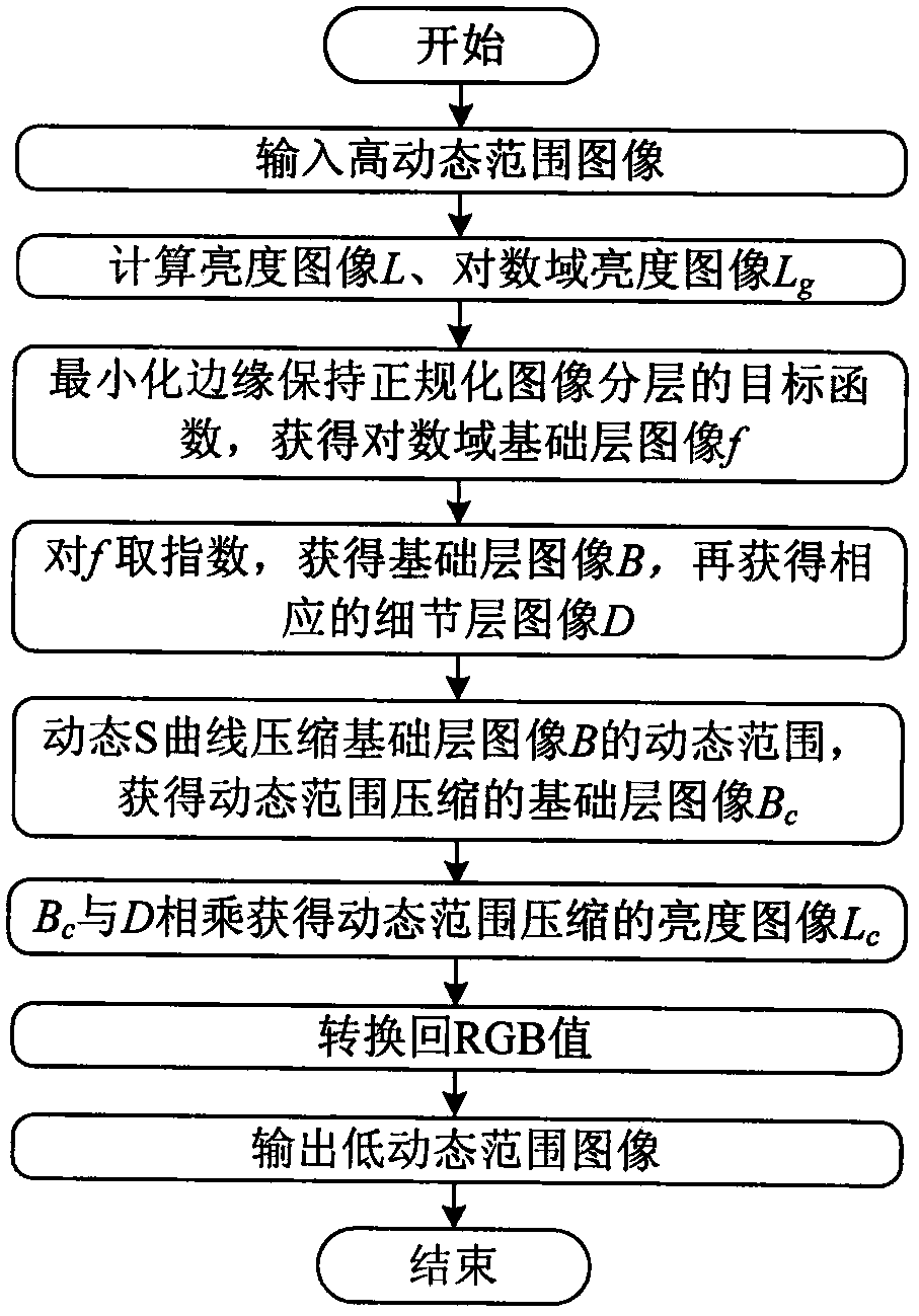
[0037] see figure 1 , the embodiment is processed in the following steps:

[0038] Step 1, read the pixel value (RGB) of the HDR image, R, G, and B are the color values ​​of the red, green, and blue channels of the HDR image respectively, and obtain its brightness image L through the conversion of RGB to Lab color space;

[0039] Step 2, take the logarithm of the brightness image L, and obtain the brightness image L in the logarithmic domain g , calculated as follows:

[0040] L g =log(max(L, 10 -6 )),

[0041] Among them, the function max( ) means to take the maximum value;

[0042] Step 3, establish an objective function based on edge-preserving regularized image layering, and decompose the logarithmic domain brig...


PUM


Abstract

The invention relates to a high dynamic range image toning mapping method based on normalized layering. The method comprises the following steps of reading one high dynamic range image, acquiring a brightness image and acquiring a logarithmic domain brightness image; establishing a target function based on edge maintenance normalization image layering, decomposing a brightness image of a logarithmic domain through minimizing the target function and acquiring a base layer image of the logarithmic domain; taking an index in the logarithmic domain base layer image to acquire the base layer image and then acquiring a corresponding detail layer image; using a dynamic S curve to compress a dynamic range of the base layer image; multiplying the base layer image with the compressed dynamic range by the detail layer image to acquire the brightness image with the compressed dynamic range; and converting back to an RGB value to acquire a low dynamic range image used for display. The method is suitable for redisplaying a high dynamic range image on a camera, a mobile phone, a display and other common terminal display devices, a halo or a toning reversion phenomenon can be avoided and a good detail reproduction capability is possessed.

Description

technical field [0001] The invention belongs to the technical field of digital image processing and is used for displaying high dynamic range images on low dynamic range output devices, in particular to a tone mapping method for high dynamic range images based on normalized layering. technical background [0002] Compared with ordinary digital imaging technology, high dynamic range imaging technology can obtain a larger exposure range, so the recorded scene is more realistic and the dynamic range of the formed image is also larger. Therefore, images obtained by this technique are generally called high dynamic range (High Dynamic Range, HDR) images. Typically, the dynamic range of an HDR image exceeds 10000:1. However, at present, the dynamic range that can be output by many image display terminal devices is relatively limited. For example, the dynamic range of LCD screens of terminal devices such as cameras, mobile phones, and monitors is generally within 100:1. The differ...

Claims


Application Information

Patent Timeline
Patent Type & Authority Patents(China)
IPC IPC(8): G06T5/00
Inventor 谢德红位春傲王琪
Owner 江苏西励科技有限公司
Learn More