Construction method for reducing temperature rise at electrician busbar lap joint part

A busbar overlapping and construction method technology, which is applied in the direction of cooling busbar devices, etc., can solve the problems of reducing electrical gaps or interphase distances, increasing the space occupied by busbars, and increasing equipment manufacturing costs, so as to increase electrical clearances or interphase distances. distance, reduce wiring width, and save resources

Active Publication Date: 2016-08-24
国网甘肃省电力公司金昌供电公司
View PDF10 Cites 11 Cited by
  • Summary
  • Abstract
  • Description
  • Claims
  • Application Information

AI Technical Summary

Problems solved by technology

Increasing the overlapping length will increase the amount of busbars, which will increase the manufacturing cost of the equipment
The bolts used for fastening will reduce the electrical clearance or phase-to-phase distance between the busbars. In order to keep the electrical clearance or phase-to-phase distance unchanged, the distance between the busbars needs to be increased, and increasing the distance between the busbars will inevitably lead to the occupation of the busbars. bigger space
[0003] How to construct and install the busbar can increase the contact area and reduce the temperature rise of the busbar, but do not reduce the electrical clearance or interphase distance, and do not increase the space occupied by the busbar

Method used


Image

  • Construction method for reducing temperature rise at electrician busbar lap joint part
  • Construction method for reducing temperature rise at electrician busbar lap joint part
  • Construction method for reducing temperature rise at electrician busbar lap joint part

Examples


Embodiment 2

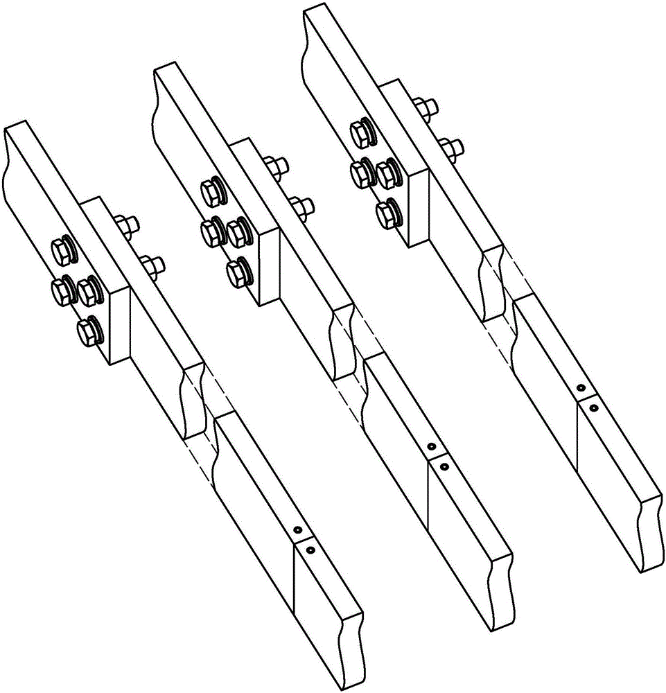
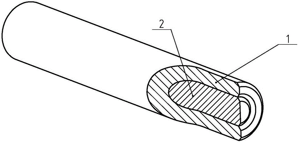
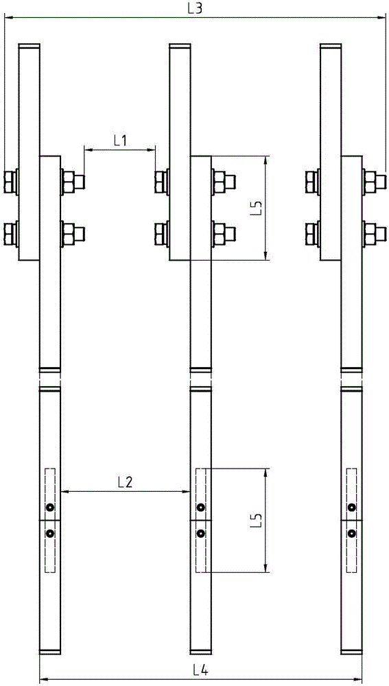
[0084] Change the copper tube in Example 1 into a copper alloy tube, and change the aluminum rod into an aluminum alloy rod. Because the hardness of the alloy is relatively high, the aluminum alloy rod can be stored for a period of time (5 minutes) in a low temperature environment (5 degrees). ), and the copper alloy tube is stored in a high temperature environment (80 degrees) for a period of time (5 minutes), with the help of thermal expansion and contraction effect, the inner diameter of the copper alloy tube can be slightly larger, while the outer diameter of the aluminum alloy rod is slightly smaller , and then conveniently assemble the aluminum alloy rod into the copper alloy tube. After the assembled connecting column returns to normal temperature, the copper alloy tube and the aluminum alloy rod can achieve interference fit. The diameter and length of the coupling column disclosed in the present invention have different specifications to meet the needs of different busb...


PUM


Abstract

The invention discloses a construction method for reducing temperature rise at an electrician busbar lap joint part, belonging to the field of electrical equipment, and specifically relates to construction and installation of an electrician busbar. The connection column is provided with a first cylindrical portion which is in interference fit with a pre-drilled hole in an electrician busbar, wherein the first cylindrical portion is provided with conductivity; a second cylindrical portion with conductivity is coaxially arranged in the first cylindrical portion; the first cylindrical portion is in interference fit with the second cylindrical portion; and the thermal expansion coefficient of the second cylindrical portion is greater than the thermal expansion coefficient of the first cylindrical portion. The connection column has the advantages that 1) the same lap joint length can generate larger conductive area, so that the current density can be reduced and the low temperature rise of the busbar can be realized; 2) the use level of the busbar is reduced so that the resource is saved; 3) the electric clearance or the phase spacing can be enlarged, so that the electrical safety of equipment is improved; and 4) the wiring width of the busbar is reduced, so that the occupied space of the busbar can be reduced.

Description

technical field [0001] The invention relates to the field of electric equipment, in particular to a construction and installation method of an electric power busbar. Background technique [0002] In the field of power distribution, the connection of two power busbars is usually overlapped and then fastened with bolts. Such as figure 1 In the upper half of the busbar, this connection method needs to overlap the two busbars by a certain length, so that the current density of the contact surface can be maintained within a certain range, so that the temperature rise at the connection can meet the relevant standards. In order to reduce the temperature rise of power equipment, it is usually necessary to increase the overlapping length of the busbars to increase the contact area, thereby reducing the current density of the contact surface, and finally making the equipment have a lower temperature rise. Increasing the overlapping length will increase the amount of busbars used, th...

Claims


Application Information

Patent Timeline
Patent Type & Authority Applications(China)
IPC IPC(8): H02G5/10
CPCH02G5/10
Inventor 不公告发明人
Owner 国网甘肃省电力公司金昌供电公司
Why Eureka
Try Eureka