Mounting suspension piece, fixing structure and assembling method for double-glass photovoltaic module

A dual-glass photovoltaic and fixed device technology, which is applied to the support structure of photovoltaic modules, photovoltaic power generation, photovoltaic modules, etc., can solve the problem of inconvenient installation, unreasonable stress on double-glass photovoltaic modules, and inconvenient installation of double-glass photovoltaic modules. problem, to achieve the effect of convenient installation, simple structure and stable clamping

Active Publication Date: 2016-08-24
POWERWAY RENEWABLE ENERGY
View PDF8 Cites 3 Cited by
  • Summary
  • Abstract
  • Description
  • Claims
  • Application Information

AI Technical Summary

Problems solved by technology

[0003] One of the purposes of the present invention is to propose a double-glass photovoltaic module installation pendant, which can solve the problem of inconvenient installation of the existing double-glass photovoltaic module and unreasonable stress on the double-glass photovoltaic module
[0004] The second purpose of the present invention is to propose a fixing device for double-glass photovoltaic modules, which can solve the problems of inconvenient installation of existing double-glass photovoltaic modules and unreasonable stress on double-glass photovoltaic modules
[0005] The third purpose of the present invention is to propose an assembly method applied to the fixing device of the double-glass photovoltaic module, which can solve the problem that the installation of the existing double-glass photovoltaic module is inconvenient, and the force of the double-glass photovoltaic module is unreasonable.

Method used


Image

  • Mounting suspension piece, fixing structure and assembling method for double-glass photovoltaic module
  • Mounting suspension piece, fixing structure and assembling method for double-glass photovoltaic module
  • Mounting suspension piece, fixing structure and assembling method for double-glass photovoltaic module

Examples


Embodiment 1

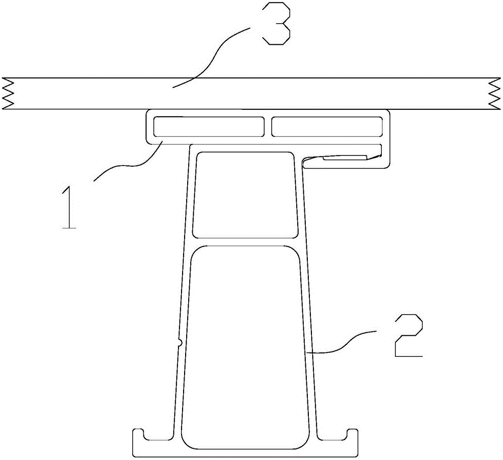
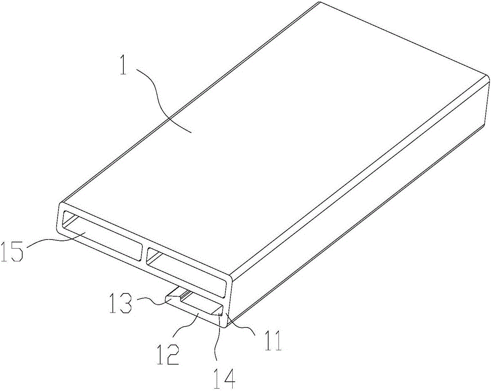
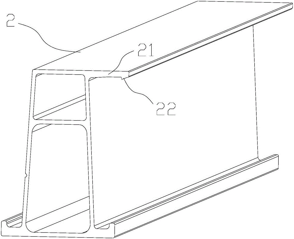
[0031] refer to Figure 1-3 , a mounting pendant for a double-glass photovoltaic module, comprising: a clamping block 1 and a sub-keel 2, the top of the clamping block 1 is a bearing part, the bearing part is bonded to the bottom of the double-glass photovoltaic module 3, and the bottom of the clamping block 1 There is a hook portion extending in a direction parallel to the bottom of the block, and a locking portion is formed between the hook portion and the bottom of the block; the top of the secondary keel 2 is provided with an extension arm 21, One end of the arm 21 is arranged on the top of the secondary keel 2, and the other end of the extension arm 21 extends outward along a direction parallel to the top of the secondary keel 2.

[0032] Wherein, the hook portion includes a first hook arm 11 and a second hook arm 12, one end of the first hook arm 11 is arranged at one end of the bottom of the block 1, and the other end of the first hook arm 11 is along the bottom of the ...

Embodiment 2

[0037] refer to Figure 1-5 , a fixing device for a double-glass photovoltaic module, comprising: a fixing bracket and a clamping block 1, the top surface of the fixing bracket is composed of at least two main keels 4 and a secondary keel 2, wherein the structure of the clamping block 1 and the secondary keel 2 is the same as The block 1 and the sub-keel 2 in Embodiment 1 have the same structure. The secondary keel 2 is fixed on the top of the main keel 3 and forms a grid-like structure with the main keel 4. A support slope is formed from one end to the other end along the length direction of the main keel 4. In this embodiment, the extension of the secondary keel 2 One end of the arm 21 is arranged on the top of the secondary keel 2 , and the other end of the extending arm 21 extends toward the higher end of the inclined plane of the bracket along a direction parallel to the top of the secondary keel 2 .

[0038] There are four clamping blocks 1 evenly distributed on the bac...

Embodiment 3

[0040] refer to Figure 1-6, an assembly method applied to the fixing device of the double-glass photovoltaic module described in embodiment 2, comprising the following steps:

[0041] Step 1, such as Figure 6 As shown, the back of the double-glass photovoltaic module 3 is divided into four parts by the center line in the length direction and the center line in the width direction of the double-glass photovoltaic module 3, and a clamping block 1 is glued to the center of each part.

[0042] Step 2. Place the fixing bracket.

[0043] Step 3. Place the double-glass photovoltaic module 3 on the sub-keel 2. Under the action of gravity, the double-glass photovoltaic module 3 slides toward the lower end of the slope of the support, and then apply external force to make the four sides on the back of the double-glass photovoltaic module 3 The clamping blocks 1 are respectively clamped into the extension arms 21 on the corresponding secondary keels 2 .

[0044] Step 4. Repeat step ...


PUM


Abstract

The invention discloses a mounting suspension piece, a fixing structure and an assembling method for a double-glass photovoltaic module. The mounting suspension piece comprises clamping blocks and secondary keels, wherein a bearing part which is used for being adhered to the double-glass photovoltaic module is arranged on the top of the corresponding clamping block; a hook part which extends along a direction parallel to the bottom of the corresponding clamping block is arranged at the bottom of the corresponding clamping block; an extension arm is arranged on each secondary keel; one end of the extension arm is arranged on the top of the corresponding secondary keel while the other end of the extension arm extends outwardly along a direction parallel to the top of the corresponding secondary keel; and a clamping part for allowing the corresponding extension arm to be inserted is formed between the hook part and the bottom of the corresponding clamping block. The mounting assembly is simple in structure, convenient to mount, and capable of forming a steady buckling relation by only moving the corresponding clamping blocks to be clamped and connected with the corresponding secondary keels; and after the double-glass photovoltaic module is mounted, the stress part of the double-glass photovoltaic module is at the bottom, and the stress part can be scattered at multiple positions at the bottom.

Description

technical field [0001] The invention relates to a mounting pendant, a fixing structure of a double-glass photovoltaic module, and an assembly method of the fixing structure. Background technique [0002] Double-glass photovoltaic modules are double-sided glass, no backsheet, and no frame structure. It has many advantages such as wear resistance, strong corrosion resistance and low water permeability. The size of the double-glass module is limited by the bearing capacity of the glass. Currently, the edge of the double-glass module is mostly fixed by pressing blocks during the installation process, and the force on the module is relatively concentrated. If you want to make a more economical For large components, it is necessary to place the fixing part of the component at the bottom of the component. Contents of the invention [0003] One of the objectives of the present invention is to provide a double-glass photovoltaic module installation pendant, which can solve the pr...

Claims


Application Information

Patent Timeline
Patent Type & Authority Applications(China)
IPC IPC(8): H02S20/00H02S30/00
CPCH02S20/00H02S30/00Y02E10/50
Inventor 陈巍周贵立李伟黄俊华
Owner POWERWAY RENEWABLE ENERGY
Why Eureka
Try Eureka