Diaphragm and centrifugal rotating machine

A rotating machinery, centrifugal technology, applied in mechanical equipment, non-variable-capacity pumps, non-displacement pumps, etc., can solve problems such as reduced compression efficiency, unstable flow, and increased pressure loss

Inactive Publication Date: 2016-08-24
MITSUBISHI HEAVY IND LTD +1
View PDF10 Cites 6 Cited by
  • Summary
  • Abstract
  • Description
  • Claims
  • Application Information

AI Technical Summary

Problems solved by technology

Therefore, although it is a state where surge does not occur, it is very close to a state where surge occurs, so the flow becomes unstable and shaft vibration may occur
In addition, in the bypass passage of Patent Document 1,

Method used


Image

  • Diaphragm and centrifugal rotating machine
  • Diaphragm and centrifugal rotating machine
  • Diaphragm and centrifugal rotating machine

Examples


Embodiment Construction

[0032] Hereinafter, an embodiment of the multistage centrifugal compressor 1 (centrifugal rotary machine) of the present invention will be described with reference to the drawings.

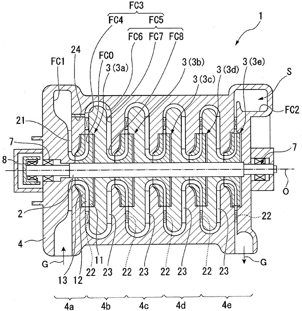
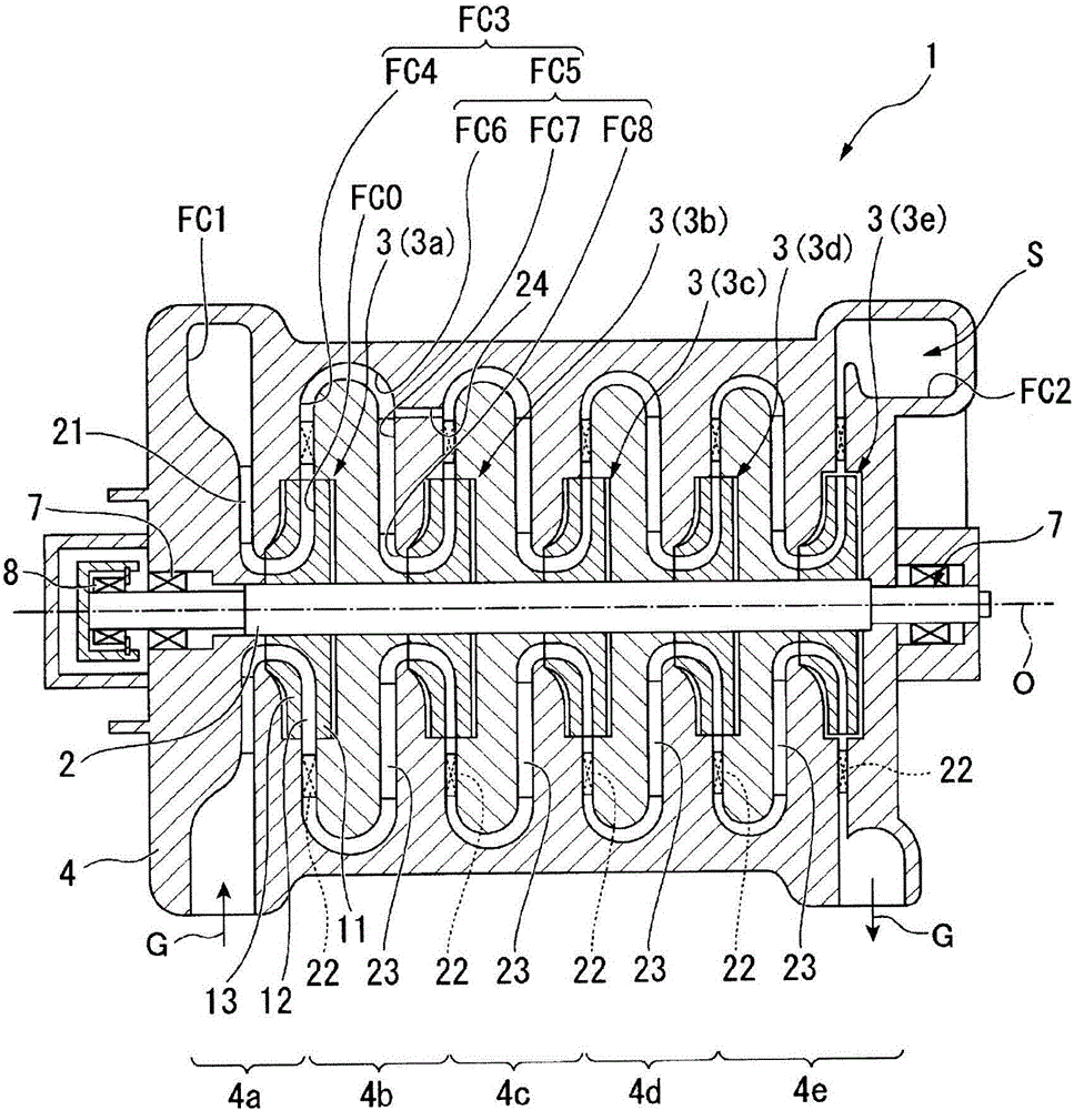
[0033] Such as figure 1 As shown, a multistage centrifugal compressor 1 includes a rotating shaft 2 rotating around an axis O, a plurality of impellers 3 attached to the rotating shaft 2, and a rotatably supported rotating shaft 2 formed to allow gas G such as air ( The shell 4 of the shell flow path FC through which fluid) flows.

[0034] The rotating shaft 2 has a cylindrical shape extending along the axis O and centered on the axis O. As shown in FIG. The rotary shaft 2 is relatively rotated around the axis O with respect to the casing 4 by a power source such as a motor (not shown).

[0035] The plurality of impellers 3 are arranged at intervals in the axis O direction where the axis O extends. In the multistage centrifugal compressor 1 of this embodiment, five impellers 3 are arranged in a...


PUM


Abstract

A diaphragm (4) covers an impeller (3) so as to be capable of rotating about an axis line (O). Formed in the diaphragm (4) are an intake flow channel (FC1) for supplying a gas (G) to an inlet of the impeller (3), a diffuser flow channel (FC4) through which gas (G) flows that has been discharged radially outward from the impeller (3), and a communication part (24) for constantly communicating the intake flow channel (FC1) and the diffuser flow channel (FC4).

Description

technical field [0001] The present invention relates to a diaphragm and a centrifugal rotary machine including the diaphragm. this application claims priority based on Japanese Patent Application No. 2014-020490 for which it applied to Japan on February 5, 2014, and uses the content here. Background technique [0002] For example, a centrifugal compressor is known as a type of centrifugal rotating machine. In a centrifugal compressor, gas is circulated in the radial direction of a rotating impeller, and the gas is compressed by centrifugal force. Among such centrifugal compressors, there is known a multistage centrifugal compressor that includes multistage impellers in the axial direction and compresses gas in stages. [0003] However, it is known that in the above-mentioned multi-stage centrifugal compressor, a phenomenon called surge occurs in which gas flows backward from the downstream side toward the upstream side in the impeller. When the flow rate of the system as ...

Claims


Application Information

Patent Timeline
IPC IPC(8): F04D29/44F04D17/12F04D29/66
CPCF04D17/122F04D29/441F04D29/682F04D27/02F04D29/286
Inventor 中庭彰宏岩本真治
Owner MITSUBISHI HEAVY IND LTD
Why Eureka
Try Eureka