Pressure sensor

A pressure sensor and pressure technology, applied in the direction of measuring fluid pressure, instruments, measuring fluid pressure through electromagnetic components, etc., can solve the problems of dynamic performance reduction, dC/dp dynamic performance loss, damage to pressure sensors, etc.

Active Publication Date: 2016-08-24
EHNDRESS KHAUZER GMBKH KO KG
View PDF8 Cites 10 Cited by
  • Summary
  • Abstract
  • Description
  • Claims
  • Application Information

AI Technical Summary

Problems solved by technology

However, this is disadvantageous for two reasons
Firstly, as the distance between the electrodes increases, the dC / dp dynamic performance decreases, and secondly, it becomes more likely to reach the fracture stress and thus damage the pressure sensor
On the other hand, a stiffer measuring diaphragm is used, which in turn causes a loss of dC / dp dynamic performance

Method used


Image

  • Pressure sensor
  • Pressure sensor
  • Pressure sensor

Examples


Embodiment Construction

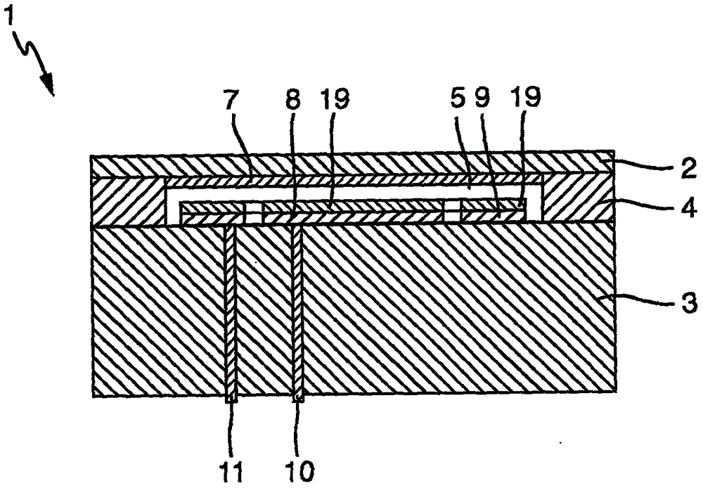
[0028] Such as figure 1 The pressure sensor 1 shown comprises a disc-shaped ceramic measuring diaphragm 2 which is connected in a pressure-tight manner along a circumferential joint 4 to a relatively rigid disc-shaped ceramic counter body 3 , whereby a measuring cavity 5 is created between the counter body 3 and the measuring diaphragm 2 . The measuring diaphragm and the counterpart contain corundum in particular. The joints especially comprise reactive brazes, such as Zr-Ni-Ti reactive brazes or glass.

[0029] The measuring diaphragm has a diaphragm electrode 7 across its entire mating body surface, for example comprising a metal layer, especially a Ta layer, wherein the electrode diameter is 2R, where R is the radius of the flexible region of the measuring diaphragm, corresponding to the inner radius of the joint. On the counterpart surface on the side of the measuring diaphragm, a central disc-shaped measuring electrode 8 is arranged, surrounded by a disc-shaped referenc...


PUM

PropertyMeasurementUnit
thicknessaaaaaaaaaa

Abstract

A pressure sensor (1) comprises a measuring diaphragm (2), which can be deformed on the basis of the pressure, and a mating body (3) which are connected to one another in a pressure-tight manner and form a measuring chamber (5) in which a reference pressure is present, wherein a pressure can be applied to an outside of the measuring diaphragm (2), wherein the pressure sensor (1) has a capacitive transducer having at least one mating body electrode (8, 9) and at least one diaphragm electrode (7), wherein, above a pressure limit value for the pressure, at least one central surface section of the measuring diaphragm (2) rests against the mating body with a contact surface (A(p)), the size of which is dependent on the pressure, wherein the pressure sensor also has a resistive transducer for converting a pressure-dependent deformation of the measuring diaphragm, when pressed in a range of values above the pressure limit value, into an electrical signal using an electrical resistance which is dependent on the contact surface of the measuring diaphragm (2) on the mating body (3).

Description

technical field [0001] The present invention relates to a pressure sensor, in particular a multi-stage pressure sensor. A capacitive pressure sensor usually includes a measuring diaphragm and a matching body, wherein the measuring diaphragm and the fitting body are connected in a pressure-tight manner along the peripheral edge, and a measuring chamber is formed between the fitting body and the measuring diaphragm, in which a reference pressure is provided. The pressure to be measured can be applied to the outside of the measuring diaphragm facing away from the measuring chamber, wherein the measuring diaphragm is deformed depending on the pressure. The pressure sensor has a capacitive transducer with at least one counterpart electrode and at least one diaphragm electrode, wherein the capacitance between the counterpart electrode and the diaphragm electrode is dependent on the pressure-dependent deformation of the measuring diaphragm. And wherein the central surface portion of...

Claims


Application Information

Patent Timeline
Patent Type & Authority Applications(China)
IPC IPC(8): G01L9/00
CPCG01L9/0051G01L9/0072
Inventor 安德烈亚斯·罗斯贝格奥拉夫·特克斯托尔艾尔玛·沃斯尼察
Owner EHNDRESS KHAUZER GMBKH KO KG
Why Eureka
Try Eureka