
Multifunctional wear-resistant eyeglass box

A glasses case, multi-functional technology, applied in the direction of clothing, small bags, luggage, etc., can solve the problems that the bottom of the bottom cover is easy to be worn, the protection performance of glasses is poor, and the function of the glasses case is single, so as to increase the lighting function and facilitate the promotion , enhance the anti-destructive effect

Inactive Publication Date: 2016-08-31
温州市优医视眼镜有限公司
View PDF7 Cites 0 Cited by
  • Summary
  • Abstract
  • Description
  • Claims
  • Application Information

AI Technical Summary

Problems solved by technology

[0002] Glasses are not only a tool for eye protection, but also a beauty decoration. Glasses should be in harmony with the facial makeup and clothing of the people of the times, and reflect the symbols of social class, elegance, fashion, etc. With the rapid development of social technology , with the continuous improvement of people's culture and living standards, and the development of vision care work, glasses will play an important role in the field of people's lives. The glasses case is a tool for holding glasses for easy portability. The bottom cover of the connection hole and the upper cover of the pivot shaft, wherein the pivot shaft of the upper cover is pivotally connected in the pivot hole of the bottom cover, so that the upper cover is pivotally connected to the bottom cover, and finally the upper cover and the bottom cover are realized. Opening and closing action. During use, users are used to placing the glasses case directly on the desk or desk. Since the bottom of the bottom cover directly touches the desktop of the desk or desk, the bottom of the bottom cover is easily worn. The existing glasses case has a single function, poor protective performance for glasses, and poor applicability. Therefore, we provide a multi-functional wear-resistant glasses case

Method used


Image

  • Multifunctional wear-resistant eyeglass box

Examples


Embodiment Construction

[0014] The preferred embodiments of the present invention will be described below in conjunction with the accompanying drawings. It should be understood that the preferred embodiments described here are only used to illustrate and explain the present invention, and are not intended to limit the present invention.

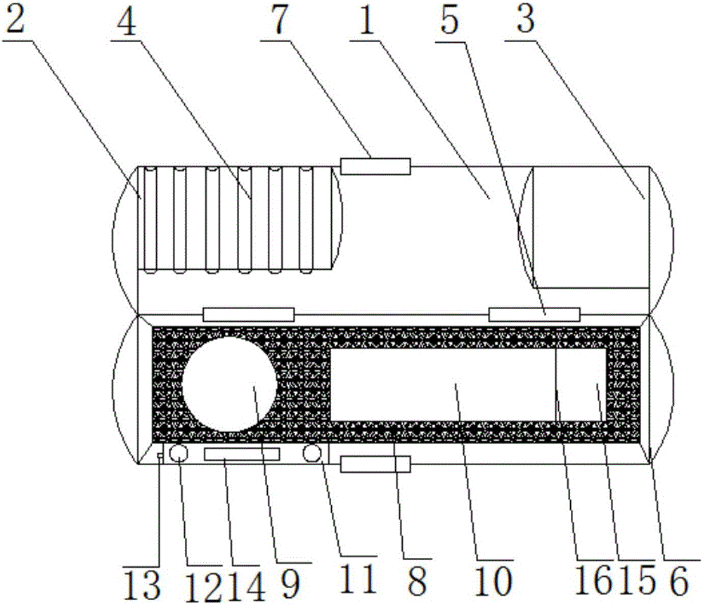
[0015] Such as figure 1 As shown, it includes an upper box body 1, and the inner cavity of the upper box body 1 is provided with a slot 2 and a mirror 3 from left to right in turn, and the slot 2 is provided with a plurality of slots 4. One side of the upper box body 1 is movably connected to the lower box body 6 through the rotating shaft 5, the same side of the upper box body 1 and the lower box body 6 is provided with a magnetic block 7, and the inner cavity of the lower box body 6 is provided with a shock-absorbing foam pad 8. The shock-absorbing foam pad 8 is sequentially provided with a contact lens groove 9, a glasses groove 10, and a mirror cloth groove 15 f...


PUM


Abstract

The invention relates to a multifunctional wear-resistant eyeglass box which comprises an upper box body. A placement clamping groove and a mirror are sequentially arranged in an inner cavity of the upper box body from left to right. A plurality of clamping groove bodies are formed in the placement clamping groove. One side of the upper box body is movably connected with a lower box body through a rotating shaft. The same sides of the upper box body and the lower box body are each provided with a magnet. A shock absorption foam cushion is arranged in an inner cavity of the lower box body and is sequentially provided with a contact lens groove, an eyeglass groove and a lens cleaner groove from left to right. A partition plate is arranged between the eyeglass groove and the lens cleaner groove. One side of the shock absorption foam cushion is provided with an illumination device box. The box bodies are controlled to be closed through the magnets. Damage caused by shake to eyeglasses is effectively avoided through the shock absorption foam cushion. The eyeglasses are fixedly placed through the contact lens groove and the eyeglass groove, the structure is reasonable, and the contact lens box and the eyeglass box are combined into a whole. Through the mirror, the eyeglasses can be conveniently taken out to be worn on eyes, time checking and make-up refining are achieved, and the eyeglass box is practical, convenient to use and diversified in function.

Description

technical field [0001] The invention relates to a multifunctional wear-resistant glasses case, which belongs to the field of daily necessities. Background technique [0002] Glasses are not only a tool for eye protection, but also a beauty decoration. Glasses should be in harmony with the facial makeup and clothing of the people of the times, and reflect the symbols of social class, elegance, fashion, etc. With the rapid development of social technology , with the continuous improvement of people's culture and living standards, and the development of vision care work, glasses will play an important role in the field of people's lives. The glasses case is a tool for holding glasses for easy portability. The bottom cover of the connection hole and the upper cover of the pivot shaft, wherein the pivot shaft of the upper cover is pivotally connected in the pivot hole of the bottom cover, so that the upper cover is pivotally connected to the bottom cover, and finally the upper co...

Claims


Application Information

Patent Timeline
Patent Type & Authority Applications(China)
IPC IPC(8): A45C11/04A45C13/36A45C15/04A45C15/06
CPCA45C11/04A45C11/046A45C13/36A45C15/04A45C15/06
Inventor 林庆两
Owner 温州市优医视眼镜有限公司
Learn More