Back flushing device for fluidized granulator filter and back flushing method thereof

A technology of fluidized granulation and backflushing equipment, which is applied in the direction of chemical instruments and methods, dispersed particle filtration, separation methods, etc., and can solve the problems of increasing the overall energy consumption of equipment, consuming manpower and material resources, etc.

Inactive Publication Date: 2016-08-31
TIANJIN YINUO PHARMA IND DESIGN CO LTD
View PDF5 Cites 2 Cited by
  • Summary
  • Abstract
  • Description
  • Claims
  • Application Information

AI Technical Summary

Problems solved by technology

[0005] The purpose of the present invention is to provide a backflushing device for the filter of a fluidized granulator, so as to solve the problem in the prior art that the filter is dedusted by using a cloth bag, and the dust intercepted by the ventilation channel inside the filter cannot be process

Method used


Image

  • Back flushing device for fluidized granulator filter and back flushing method thereof
  • Back flushing device for fluidized granulator filter and back flushing method thereof
  • Back flushing device for fluidized granulator filter and back flushing method thereof

Examples


Embodiment 1

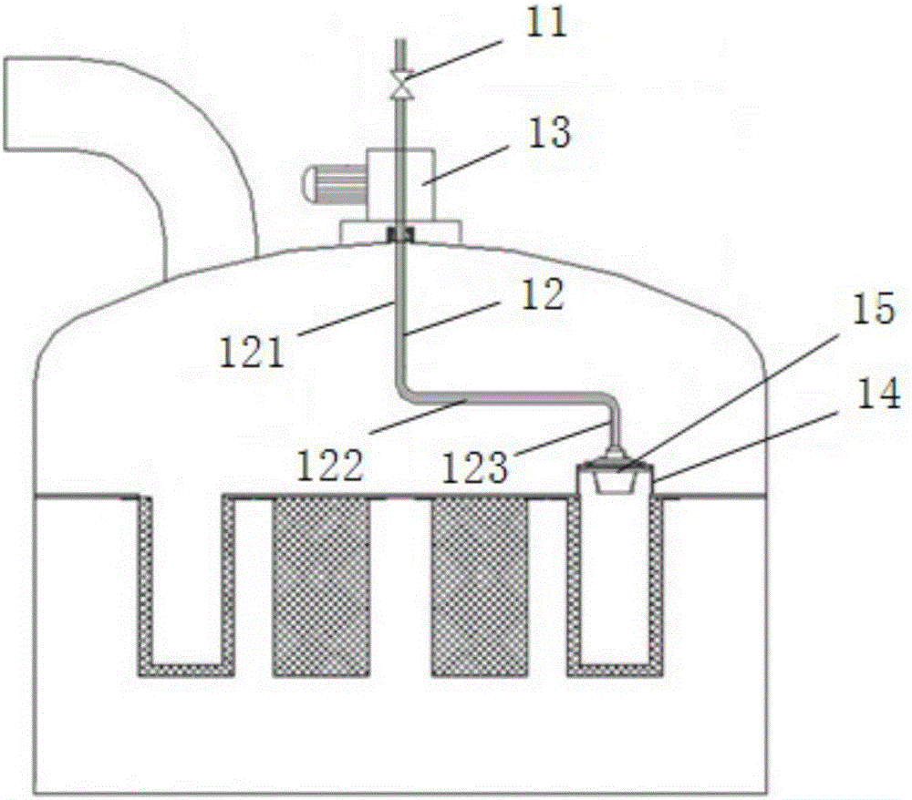
[0039] figure 1 A structural schematic diagram of a backflushing device for a fluidized granulator filter provided in an embodiment of the present invention; figure 1 As shown, the backflushing device of a fluidized granulator filter provided in this embodiment includes: a compressed air control valve 11 connected to a compressed air generating device, a compressed air pipeline 12, a rotary indexing motor 13 and a sealing device 14;

[0040] The compressed air control valve 11 is connected to the compressed air pipeline 12, the rotary indexing motor 13 controls the rotation of the compressed air pipeline 12, the compressed air pipeline 12 drives the rotation of the sealing device 14, and the sealing device 14 is used to seal the filter The chamber is sealed.

[0041] One end of the compressed air pipeline 12 is connected to the compressed air control valve 11, and the other end of the compressed air pipeline 12 is connected to the sealing device 14. There may be multiple sea...

Embodiment 2

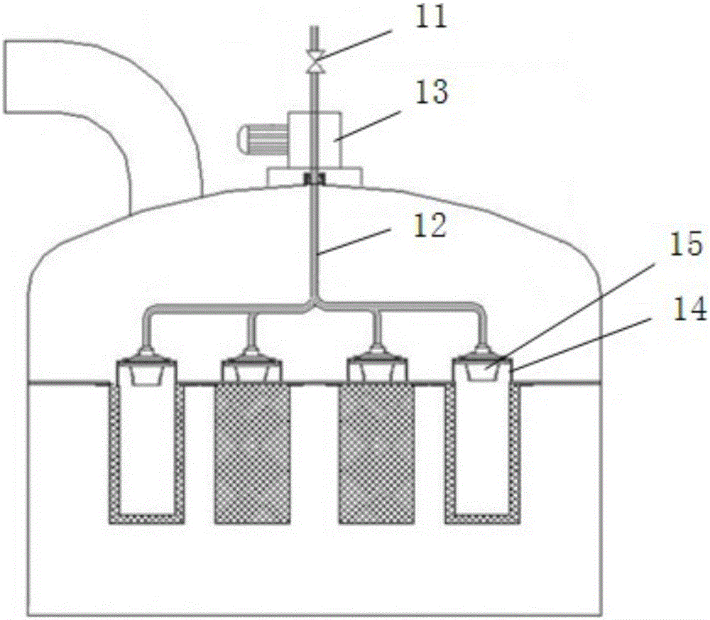
[0061] figure 2 A structural schematic diagram of a backflushing device for a fluidized granulator filter provided in another embodiment of the present invention; figure 2 As shown, the backflushing device of a fluidized granulator filter provided in this embodiment includes: a compressed air control valve 11 connected to a compressed air generating device, a compressed air pipeline 12, a rotary indexing motor 13 and a sealing device 14;

[0062] The compressed air control valve 11 is connected to the compressed air pipeline 12, the rotary indexing motor 13 controls the rotation of the compressed air pipeline 12, the compressed air pipeline 12 drives the rotation of the sealing device 14, and the sealing device 14 is used to seal the filter The chamber is sealed.

[0063] The difference between this embodiment and Embodiment 1 is that the compressed air pipeline 12 is set to have a pipeline inlet in the upper part and a disc shape with multiple pipeline outlets in the lowe...


PUM

PropertyMeasurementUnit
Rotation angleaaaaaaaaaa

Abstract

The invention provides a back flushing device for a fluidized granulator filter. The back flushing device comprises a compressed air control valve connected with a compressed air generating device, a compressed air pipeline, a rotating indexing motor and a sealing device, wherein the compressed air control valve is connected with a compressed air pipeline; the compressed air pipeline is controlled to rotate by the rotating indexing motor; the sealing device is driven to rotate by the compressed air pipeline; the sealing device is used for blocking the cavity of the filter. A back flushing method comprises the following steps of: (i) locating the sealing device; (ii) filling the compressed air; (iii) releasing the compressed air; and (iv) completing the back flushing of the filter. The rotating indexing motor of the back flushing device provided by the invention is used for driving the compressed air pipeline to rotate; the sealing device is driven to rotate by the compressed air pipeline; a plurality of sealing devices can be arranged, so that the purpose of simultaneously back flushing a plurality of filter cavities can be achieved; the discontinuous circulating back flushing process can be performed, so that the de-dusting effect is achieved.

Description

technical field [0001] The invention relates to the technical field of backflushing devices, in particular to a backflushing device for a fluidized granulator filter and a backflushing method for the device. Background technique [0002] At present, in the fields of pharmacy, food, chemical industry, metallurgy and other fields, fluidized manufacturing equipment, fluidized coating or pneumatic conveying devices are used. Fluidized bed granulation generally refers to top spray fluidized bed, and its main structure includes containers, Air distribution plate, nozzle, filter bag, air inlet and outlet, and material outlet. When the fluidized bed granulator is used, compressed air and binder solution are atomized by the nozzle in a certain proportion and sprayed onto the fluidized bed. On the material powder that is in a fluidized state, the liquid droplets wet the contacted powder and coalesce around it to form a particle nucleus. The effect is to make the particle core and the...

Claims


Application Information

Patent Timeline
IPC IPC(8): B01D46/04B01D46/02B01J2/16
CPCB01D46/023B01D46/04B01J2/16B01D46/72B01D46/71
Inventor 刘春明王世庆刘晓亮
Owner TIANJIN YINUO PHARMA IND DESIGN CO LTD
Why Eureka
Try Eureka