
Welding rod shearing machine capable of adjusting shearing length

A technology for shearing machines and welding rods, which is applied in the direction of shearing devices, attachments of shearing machines, knives for shearing machines, etc. It can solve the problems of low shearing efficiency, inconvenient adjustment and operation, etc., and achieve high shearing efficiency , Easy to adjust and ensure the effect of reliability

Active Publication Date: 2016-08-31
HANGHOU ACAD OF MACHINERY SCI & TECHCO +1
View PDF9 Cites 3 Cited by
  • Summary
  • Abstract
  • Description
  • Claims
  • Application Information

AI Technical Summary

Problems solved by technology

[0004] The invention overcomes the inconvenient operation of the existing cutting equipment for adjusting the cutting length of the welding rod, can only cut the welding rod of a specific length, and has low cutting efficiency, and provides a welding rod shearing machine with adjustable cutting length , it can easily adjust the cutting length of the welding rod, and can cut any length of welding rod according to the needs. The cutting length of the welding rod is easy to adjust and the cutting efficiency is high.

Method used


Image

  • Welding rod shearing machine capable of adjusting shearing length
  • Welding rod shearing machine capable of adjusting shearing length
  • Welding rod shearing machine capable of adjusting shearing length

Examples


Embodiment

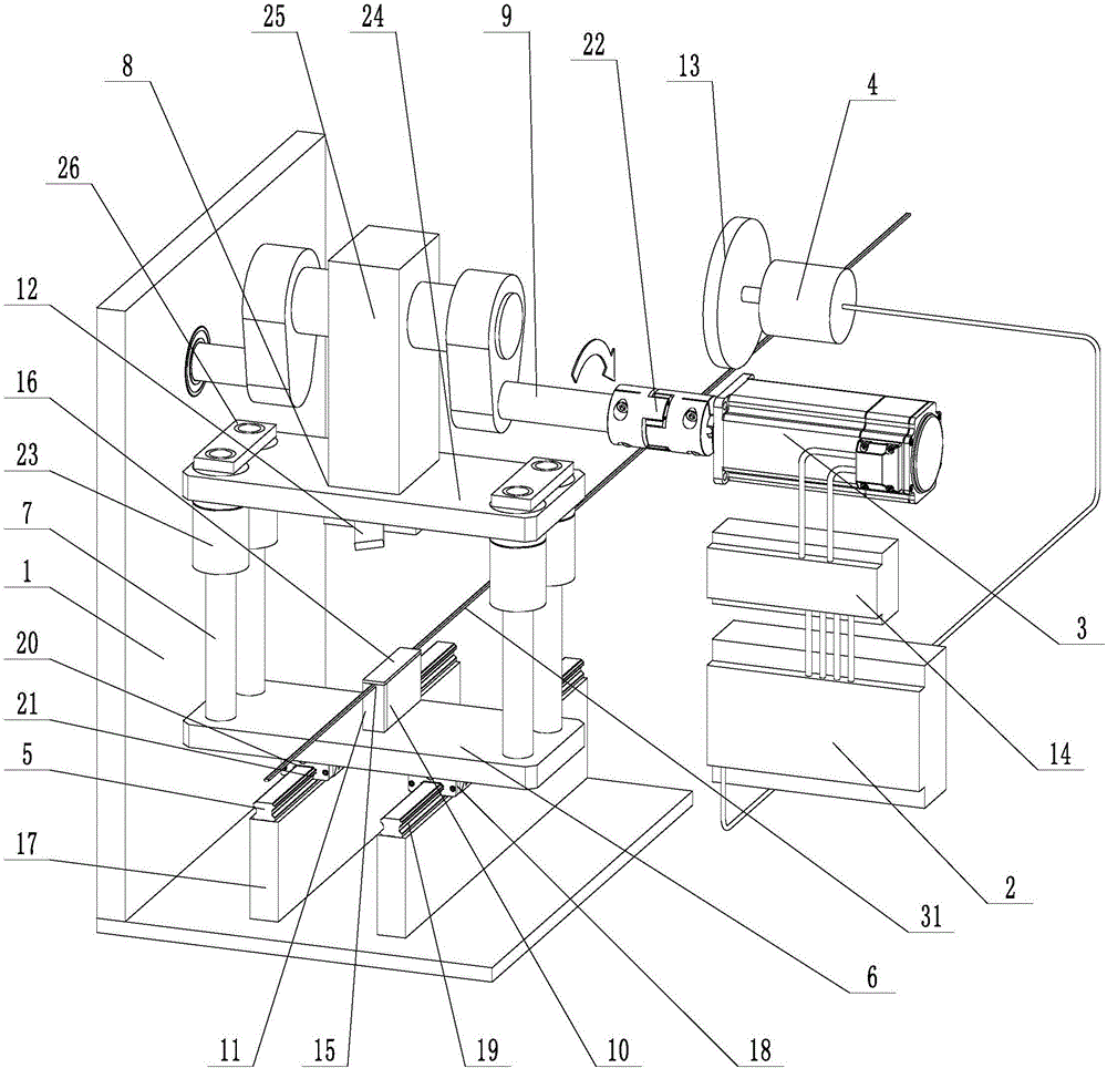
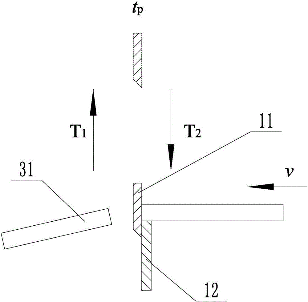
[0021] Embodiment: a kind of electrode cutter with adjustable cutting length (see attached figure 1 , attached figure 2 ), including frame 1, PLC controller 2, drive motor 3, and photoelectric encoder 4. The frame is in an L-shaped structure, and a linear guide rail 5 is installed on the frame. The linear guide rail is installed on the bottom surface of the frame, and the linear guide rail can be The sliding adapter is connected with the lower mounting seat 6, and the bottom surface of the frame is fixedly connected with two supporting vertical plates 17 arranged in parallel, and two linear guide rails are installed on the two supporting vertical plates respectively. There are two sliding guide bars 18 correspondingly connected to the linear guide rail on the lower surface of the lower mounting seat, and concave guide grooves 19 are provided on both outer surfaces of the linear guide rail, and sliding guide bars adapted to the linear guide rail are provided on the lower surfa...


PUM


Abstract

The invention discloses a welding rod shearing machine capable of adjusting shearing length. The welding rod shearing machine aims at overcoming the defects that existing shearing equipment is inconvenient to adjust and operate the welding rod shearing length and low in shearing efficiency. The welding rod shearing machine comprises a rack, a PLC controller, a driving motor and a photoelectric encoder. A linear guide rail is installed on the rack. A lower installation base is slidably connected to the linear guide rail in a matched mode and provided with a plurality of vertical guide rods. An upper installation base is arranged above the lower installation base and connected to the vertical guide rods in a lifting and sleeving mode. A crank shaft is connected to the upper installation base and is in transmission connection with an output shaft of the driving motor. The lower installation base is provided with a clamping block used for clamping a welding rod. A lower blade is installed on the side surface of the clamping block. An upper blade is installed at the lower end of the upper installation base. A friction wheel used for making contact with the surface of the welding rod is installed on the photoelectric encoder. The driving motor is electrically connected with a motor controller. The motor controller and the photoelectric encoder are both electrically connected with the PLC controller.

Description

technical field [0001] The present invention relates to a shearing device, more particularly, it relates to a welding rod shearing machine with adjustable cutting length. Background technique [0002] At present, the commonly used welding rod shearing equipment impacts the welding rod intermittently through two impact blocks, so as to achieve the purpose of shearing. In the actual welding operation process, different welding positions have different requirements for the length of the electrode, and there are differences in the length specifications of the electrodes that need to be cut for different types of electrodes. Therefore, the electrodes often need to be cut into different shapes during the actual cutting process. length specification. However, it is difficult for many welding rod shearing equipment to adjust the cutting length conveniently, which is not conducive to enterprises to improve production efficiency and quickly adapt to market changes. [0003] Chinese ...

Claims


Application Information

Patent Timeline
Patent Type & Authority Applications(China)
IPC IPC(8): B23D15/04B23D33/02B23D33/00B23D35/00
CPCB23D15/04B23D33/006B23D33/02B23D35/00
Inventor 许岚范仲华唐卫岗邵碧璐杨文俊朱家阳
Owner HANGHOU ACAD OF MACHINERY SCI & TECHCO
Learn More