Elevator buffer

A technology for buffers and elevators, applied in springs/shock absorbers, elevators, vibration suppression adjustments, etc., can solve the problems of passenger casualties, poor buffering effect, poor buffering performance, etc., to achieve guaranteed buffering effect, good buffering effect, and high performance stable effect

Inactive Publication Date: 2016-08-31
AMSON ELEVATOR
View PDF7 Cites 5 Cited by
  • Summary
  • Abstract
  • Description
  • Claims
  • Application Information

AI Technical Summary

Problems solved by technology

[0002] Nowadays, elevators are indispensable no matter in shopping malls, residences or hospitals, etc. It is also common for elevators to break down. After a long time, elevators stop running due to minor problems. You can wait for professionals to solve the problem. Sometimes because there is no maintenance, Once the elevator wire rope is disconnected, the elevator may directly and rapidly descend. Currently, the commonly used buffers for buffering can play a certain buffering effect on the elevator, but the stalled and falling elevator car and the buffer When in contact, the vibration and impact force generated by the impact can be directly transmitted to the elevator car, so it is easy to cause casualties to passengers in the elevator car
At the same time, due to the limitation of its structure, the buffer stroke of the traditional elevator buffer device is small, so the buffer performance is poor
Moreover, the buffers commonly used at present are not fixed by brackets, and there are cases where the buffer is tilted under pressure and cannot play the role of buffering.
At present, the materials used in the commonly used collision parts have poor cushioning effect and the effect is not very good.

Method used


Image

  • Elevator buffer

Examples


Embodiment Construction

[0015] The present invention will be further described below in conjunction with the drawings. The following embodiments are only used to illustrate the technical solutions of the present invention more clearly, and cannot be used to limit the protection scope of the present invention.

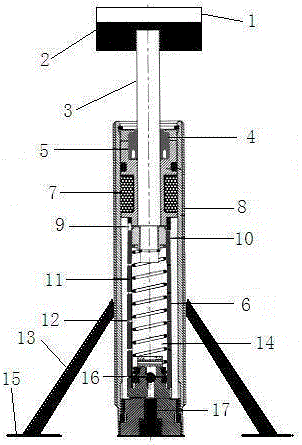
[0016] Such as figure 1 The elevator buffer shown includes an impact head 2 and a body 8, which is characterized in that the body 8 is movably connected to the impact head 2 through an axis 3, and the upper part of the impact head 2 is closely fixed to a buffer head 1. The shell of the buffer head 1 adopts a plastic shell. The buffer head 1 is equipped with an airbag, which will be inflated and popped after being impacted, which has a good buffering effect; the bottom end of the body 8 is fixed on the ground, The body is also fixed on the ground through two brackets 13, one end of the bracket 13 is welded to the middle and lower section of the body 8, and the other end is fixed on the ground thr...


PUM


Abstract

The invention discloses an elevator buffer. The elevator buffer comprises a collision head and a body. The elevator buffer is characterized in that the body is movably connected with the collision head through an axis; a buffering head is closely attached and fixed to the upper portion of the collision head, and a plastic shell is adopted as a shell of the buffering head, and a safety airbag is arranged in the buffering head and can be inflated and pop up after being subjected to collisions; the bottom end of the body is fixed to the contact ground; the body is further fixed to the contact ground through a support, wherein one end of the support is welded to the lower middle section of the body, and the other end of the support is fixed to the contact ground through a fixing piece; and a hydraulic buffer is adopted as the buffer. The elevator buffer has the advantages that firstly, the safety airbag is adopted at the collision part and can pop up after being subjected to collisions, and a very good buffering function is achieved; secondly, the elevator buffer is protected, and the situation that the elevator buffer is stressed, consequently, the elevator buffer is laterally inclined or topples down, and the buffering function is lost is prevented; thirdly, the space needed for operation is small; and fourthly, raw materials needed for the hydraulic buffer are oil or other liquid, and therefore compared with other buffers, the manufacturing cost is much lower.

Description

Technical field [0001] The invention relates to an elevator buffer, belonging to the technical field of elevator safety protection. Background technique [0002] Nowadays, elevators are indispensable in shopping malls, residences, hospitals, etc. It is also common for elevators to break down. The elevator has been used for a long time and can stop running when encountering minor problems. You can wait for professionals to solve the problem, sometimes because there is no maintenance. Once the elevator cable is disconnected, the elevator has the possibility of directly descending quickly. The buffers commonly used at present can buffer the elevator to a certain extent, but the elevator car and the buffer that have stalled and fallen When in contact, the vibration and impact force generated by the impact can be directly transmitted to the elevator car, so it is easy to cause casualties of passengers in the elevator car. At the same time, due to the limitation of its structure, the ...

Claims


Application Information

Patent Timeline
IPC IPC(8): B66B5/28F16F15/023
CPCB66B5/282F16F15/0232
Inventor 夏平
Owner AMSON ELEVATOR
Why Eureka
Try Eureka