
Hybrid girder cable-stayed bridge closure front girder body pre-bias pushing device

A technology of jacking devices and cable-stayed bridges, which is applied in the direction of cable-stayed bridges, bridges, bridge forms, etc., can solve the problems affecting the quality and safety of the project, and the additional cable force of the short cable exceeds the limit, so as to achieve good environmental protection effect, save materials, Simple operation effect

Active Publication Date: 2016-08-31
THE THIRD ENG CO LTD OF THE HIGHWAY ENG BUREAU OF CCCC
View PDF9 Cites 2 Cited by
  • Summary
  • Abstract
  • Description
  • Claims
  • Application Information

AI Technical Summary

Problems solved by technology

[0002] In the closing construction of hybrid girder cable-stayed bridges, it is necessary to consider the influence of the temperature environment on the closing. Generally, the method of temperature closing is adopted, that is, the closing temperature is specified, and the width of the closing mouth at this temperature is used as the length of the closing section. This method is very important for the design closing temperature. It is very convenient to close the dragon in the environment or close to the design temperature environment. After the bridge is completed, the internal force of the beam, the cable force and the offset of the tower top are all consistent with the design; but for the closure in the low temperature environment, the forced displacement of the beam body after the bridge is completed The quantity will easily cause the additional cable force of the short cable to exceed the limit, which will affect the quality and safety of the project, which has great limitations.

Method used


Image

  • Hybrid girder cable-stayed bridge closure front girder body pre-bias pushing device
  • Hybrid girder cable-stayed bridge closure front girder body pre-bias pushing device

Examples


Embodiment Construction

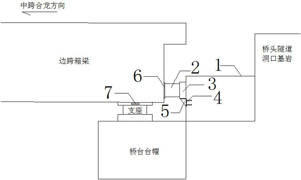
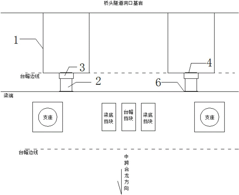
[0022] First, two concrete bases are symmetrically set up with concrete and steel bars at the end of the abutment girder body, and steel plates are pre-embedded in the base corresponding to the beam body pushing position (web plate), and triangular corbel supports are welded on the pre-embedded steel plates, and will be used The force transmission column made of steel plate is placed on the support of the corbel, and the jack (500t) is lifted by the lifting device (2t chain hoist). The rear end of the jack is against the force transmission column, and at the same time, place Steel backing plate, after the jacks of the two bases are in place, start the jacks to support the beam body. After calculating the beam pre-deflection and jacking force, start the jack for test jacking, and set up the beam displacement observation device at the same time, that is, use the level instrument to observe the displacement observation marks on the side of the wedge at the bottom of the beam outsi...


PUM


Abstract

The invention discloses a hybrid girder cable-stayed bridge closure front girder body pre-bias pushing device. The hybrid girder cable-stayed bridge closure front girder body pre-bias pushing device is characterized in that the end of a bridge abutment girder body is symmetrically provided with two concrete bases with concrete and rebars, and steel plates are embedded in the positions, corresponding to girder pushing positions, of the inside of the bases; triangular bracket supports are welded to the embedded steel plates, and force transferring columns made of steel plates are placed on the bracket supports; and jacks are lifted through lifting device bodies, the back ends of the jacks abut against the force transferring columns, and meanwhile a steel base plate is placed between the oil cylinder end of each jack and the girder body. After a low-temperature closure condition is prepared, formal pre-bias pushing is started, the two jacks synchronously conduct pushing at the constant speed till the girder body pre-bias value meets design and calculation requirements, loads are held till mid-span closure locking is completed, and the jacks are dismantled. By means of the hybrid girder cable-stayed bridge closure front girder body pre-bias pushing device, on the premise that the safety and the quality of construction are ensured, the construction period is overall shorted by two months.

Description

technical field [0001] The invention relates to a pre-deflection and pushing device for a front girder body of a cable-stayed bridge. Background technique [0002] In the closing construction of hybrid girder cable-stayed bridges, it is necessary to consider the influence of the temperature environment on the closing. Generally, the method of temperature closing is adopted, that is, the closing temperature is specified, and the width of the closing mouth at this temperature is used as the length of the closing section. This method is very important for the design closing temperature. It is very convenient to close the dragon in the environment or close to the design temperature environment. After the bridge is completed, the internal force of the beam, the cable force and the offset of the tower top are all consistent with the design; but for the closure in the low temperature environment, the forced displacement of the beam body after the bridge is completed The amount will...

Claims


Application Information

Patent Timeline
IPC IPC(8): E01D21/00E01D11/04
CPCE01D11/04E01D21/00
Inventor 李文陆海军刘方华李庆华王宇
Owner THE THIRD ENG CO LTD OF THE HIGHWAY ENG BUREAU OF CCCC
Learn More