Water valve structure of humidifier and upper water adding humidifier applying water valve structure

A humidifier and water valve technology, applied in the application, heating method, control valve and other directions, can solve the problems of overflow, leakage danger, easy to overflow, etc. Effect

Active Publication Date: 2016-08-31
FOSHAN SHUNDE DEERMA ELECTRIC APPLIANCES CO LTD
View PDF8 Cites 17 Cited by
  • Summary
  • Abstract
  • Description
  • Claims
  • Application Information

AI Technical Summary

Problems solved by technology

However, the pressure in the water tank of the top-filling humidifier is affected by the atmospheric pressure, and water is prone to overflow between the water tank and the base of the humidifier. It is necessary to set up a water valve structure that effectively controls water replenishment to keep the humidifier in working condition.
If the control of the water is not accurate and the water is too much, there will be overflow and the danger of electric leakage; if the water cannot be replenished in time, there will be dangerous situations such as burning out
Therefore, the setting requirements for the control device of the water valve have become a difficult problem in the development of the current top-filling humidifier.

Method used


Image

  • Water valve structure of humidifier and upper water adding humidifier applying water valve structure
  • Water valve structure of humidifier and upper water adding humidifier applying water valve structure
  • Water valve structure of humidifier and upper water adding humidifier applying water valve structure

Examples


Embodiment Construction

[0024] A water valve structure of a humidifier according to the present invention and an upper water-filling humidifier using the water valve structure are described in conjunction with the accompanying drawings.

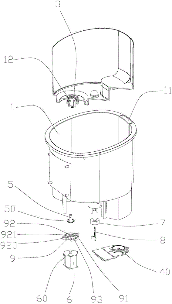
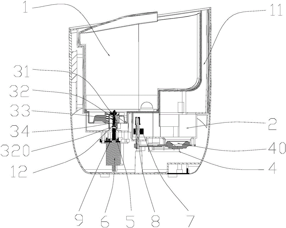
[0025] Such as Figures 1 to 6 As shown, the top-filling humidifier includes a top-filling water tank 1 and a steam generating chamber 2. The water tank 1 includes a water inlet, a nozzle, a steam pipe 11 and a water outlet pipe 12 at the bottom. One end of the steam pipe 11 is connected to the nozzle The other end is connected to the steam generating chamber 2; the outlet pipe 12 of the water tank 1 is provided with a water valve 3; the steam generating chamber 2 is provided with a steam generator 4 and a water level control device, and the water level control device According to the change of the water level in the steam generating chamber 2, the water valve 3 is opened or closed to control the amount of water entering the steam generating chamber 2.

[0026] Spe...


PUM


Abstract

The invention discloses a water valve structure of a humidifier and an upper water adding humidifier applying the water valve structure. The water valve structure comprises a water draining valve mounted on a water tank drain pipe, and a water level control device arranged in a steam generation cavity; the water level control device includes an ejector rod, an electromagnetic valve and a floater switch connected with the electromagnetic valve; the ejector rod is positioned below the water draining valve; the floater switch includes a floater and a reed switch mutually sleeved; the reed switch is connected with the electromagnetic valve; the floater is provided with a magnetic piece for controlling magnetic suction of the reed switch; the floater is displaced up and down along with the water level change; and when the position of the floater is lower than the reed switch, the electromagnetic valve is started to eject up the ejector rod, and the water draining valve is located in a drain state. The water valve structure precisely controls the quantity of water in the steam generation cavity, timely replenishes the water in water shortage, timely stops drainage in water saturation, effectively prevents the condition of easy water overflowing of the humidifier or water shortage dryout, and enables users to safely use the humidifier.

Description

technical field [0001] The invention relates to the field of steam household appliances, in particular to a water valve structure of a humidifier and an upper-filling type humidifier using the water valve structure. Background technique [0002] With the development of science and technology, people's living standards are improving day by day, and people's requirements for living environment are gradually increasing. Among them, air humidity is one of the important factors affecting comfort, especially in northern China and places where air conditioners are used for a long time, the environment is very dry, and corresponding equipment should be used to increase the humidity of the air to adjust a comfortable living environment. Therefore, humidification equipment is more and more popular with families and has become a must-have small household appliance in the home. [0003] Humidifiers currently on the market are generally composed of a water tank and a steam generating ch...

Claims


Application Information

Patent Timeline
Patent Type & Authority Applications(China)
IPC IPC(8): F16K15/18F24F13/00
CPCF16K15/18F24F13/00
Inventor 蔡演强
Owner FOSHAN SHUNDE DEERMA ELECTRIC APPLIANCES CO LTD
Why Eureka
Try Eureka