Waste heat collecting cover of cooking range

A technology of waste heat collection and collection cover, which is applied in water heaters/stoves, household furnaces/stoves, household heating, etc. It can solve the problems of low heat utilization rate, waste of resources, small kitchen area, etc., and achieve high heat utilization rate , saving resources, and easy to use

Inactive Publication Date: 2016-08-31
马志强
View PDF10 Cites 0 Cited by
  • Summary
  • Abstract
  • Description
  • Claims
  • Application Information

AI Technical Summary

Problems solved by technology

[0002] Currently used stoves, the junction of the heating area and the heating surface are generally open, the heat absorbed by the heating body or the heating surface is only about 20% of the heat generated by the fuel, and the remaining 80% of the heat is dissipated in the kitchen air through the opening. It leads to high temperature in the kitchen, low heat utilization rate, waste of resources, and inconvenient use
Secondly, although there a

Method used


Image

  • Waste heat collecting cover of cooking range
  • Waste heat collecting cover of cooking range
  • Waste heat collecting cover of cooking range

Examples


Embodiment 1

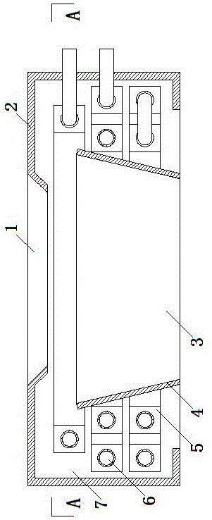
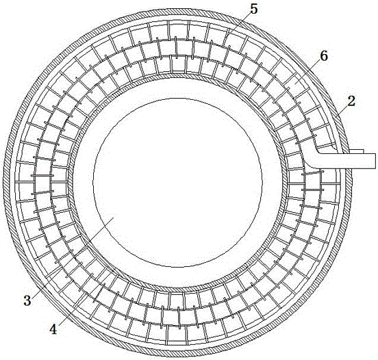
[0023] Embodiment one: if figure 1 , figure 2 As shown, the stove waste heat collection cover of the present invention includes a collection cover 2 , an isolation layer 4 and a heat exchange water pipe 6 . The top of the collection cover 2 is provided with a placement opening 1 for placing a heating body, and the bottom is provided with an opening for entering a stove burner. The placement opening 1 on the top of the collection cover 2 is closed by a heating body. Collect the opening at the bottom of the hood 2 and place it on the stove. The isolation layer 4 is placed in the collection hood 2 to divide the space in the collection hood 2 into a heating zone 3 and a waste heat collection zone 7 , so that the burner port of the stove is placed in the heating zone 3 . The tops of the heating zone 3 and the waste heat collection zone 7 communicate with each other, and the waste heat used for the heating zone 3 enters the waste heat collection zone 7 from the top of the heatin...

Embodiment 2

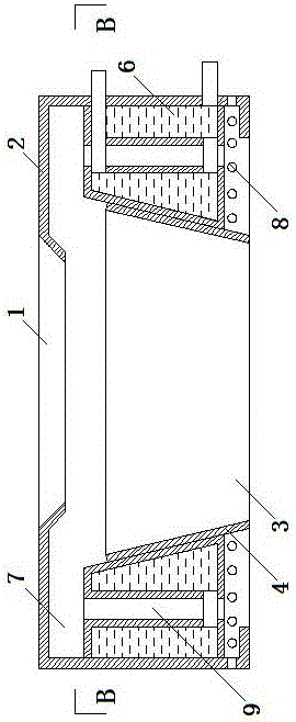
[0026] Embodiment two: if image 3 , Figure 4 As shown, the heat exchange water pipe 6 is a concave pipe. The heat exchange water pipe 6 is provided with a heat collecting tank 9 . The tank bottom of the heat collecting tank 9 communicates with the bottom of the waste heat collecting area 7, and the waste heat stays in the heat collecting tank for a long time, which increases the heat absorbing area of ​​the heat exchange water pipe 6, and the waste heat is more fully utilized and the thermal efficiency is higher. A circulation hole 8 is provided at the bottom of the wall of the waste heat collection area 7 for exhaust gas discharge.


PUM


Abstract

The invention discloses a waste heat collecting cover of a cooking range. The waste heat collecting cover comprises a collecting cover body, an isolation layer and a heat exchange water pipe; the top and the bottom of the collecting cover body are each provided with an opening, and the opening in the top of the collecting cover body is sealed through a heating body; the opening in the bottom of the collecting cover body, and the collecting cover body is placed on the cooking range; the isolation layer is arranged in the collecting cover body to separate space in the collection cover body into a heating area and a waste heat collecting area, and a fire spraying opening of the cooking range is placed in the heating area; the top of the heating area and the top of the waste heat collecting area are communicated, and waste heat for the heating area enters the waste heat collecting area from the top of the heating area; the heat exchange water pipe is arranged in the waste heat collecting area; and the heat exchange water pipe is arranged around the isolation layer, one end of the heat exchange water pipe stretches out of the collecting cover body to be communicated with a water source, and a discharging opening controlled by a valve is formed in the position, arranged on the collecting cover body, of the other end of the heat exchange water pipe.

Description

technical field [0001] The invention relates to waste heat utilization equipment, in particular to a stove waste heat collection cover. Background technique [0002] Currently used stoves, the junction of the heating area and the heating surface are generally open, the heat absorbed by the heating body or the heating surface is only about 20% of the heat generated by the fuel, and the remaining 80% of the heat is dissipated in the kitchen air through the opening. As a result, the temperature in the kitchen is high, the heat utilization rate is low, resources are wasted, and use is inconvenient. Secondly, although there are stoves that collect waste heat at present, because the device for collecting waste heat is integrated with the stove, the volume of the stove is large, limited by the small area of ​​ordinary family kitchens, it cannot be popularized, and it is inconvenient; It is integrated with the stove and cannot be separated, so that the stove in use without the wast...

Claims


Application Information

Patent Timeline
IPC IPC(8): F24C13/00
CPCF24C13/00
Inventor 马志强
Owner 马志强
Why Eureka
Try Eureka