Image forming apparatus

An image and toner image technology, applied in the field of image forming devices, can solve the problems of small magnetic shielding, inability to adapt to size, and redundant space

Inactive Publication Date: 2009-09-30
KYOCERA DOCUMENT SOLUTIONS INC
View PDF3 Cites 8 Cited by
  • Summary
  • Abstract
  • Description
  • Claims
  • Application Information

AI Technical Summary

Problems solved by technology

[0006] However, the movable range of the magnetic member of the first prior art is large, and extra space is required for this, which inadvertently leads to an increase in the size of the entire device
[0007] On the other hand, the second prior art cannot accommodate more paper sizes because the shielding area and the non-shielding area are determined by using the positions of the steps formed in advance on the shielding plate.
In addition, when steps are provided in the rotation direction of the shielding plate, due to the restriction of the overall rotation angle, each step cannot be too large (for example, the rotation angle is about 15 degrees to 30 degrees), so the magnetic shielding capacity is small, resulting in no Sufficient heat suppression

Method used


Image

  • Image forming apparatus
  • Image forming apparatus
  • Image forming apparatus

Examples


no. 1 approach

[0066] Details of the fixing unit

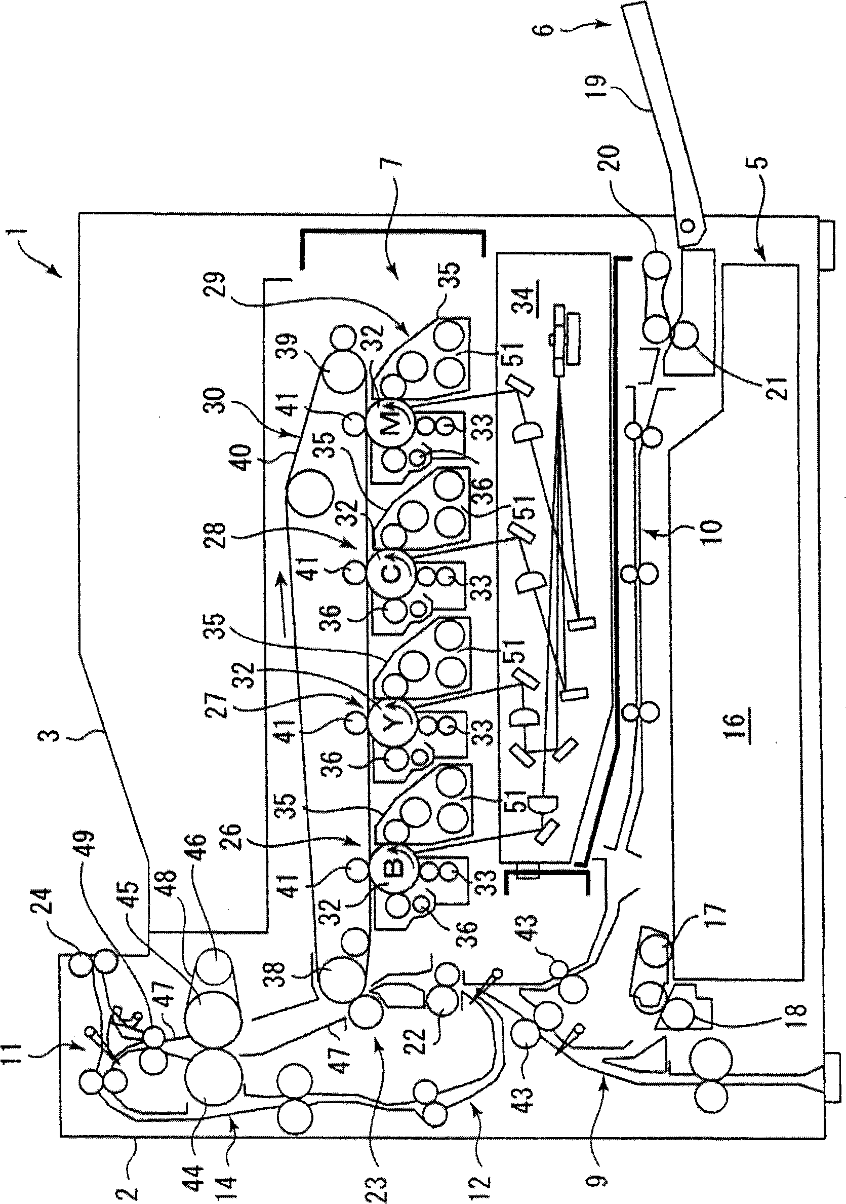
[0067] The fixing unit 14 used in the first embodiment of the image forming apparatus 1 will be described in detail below.

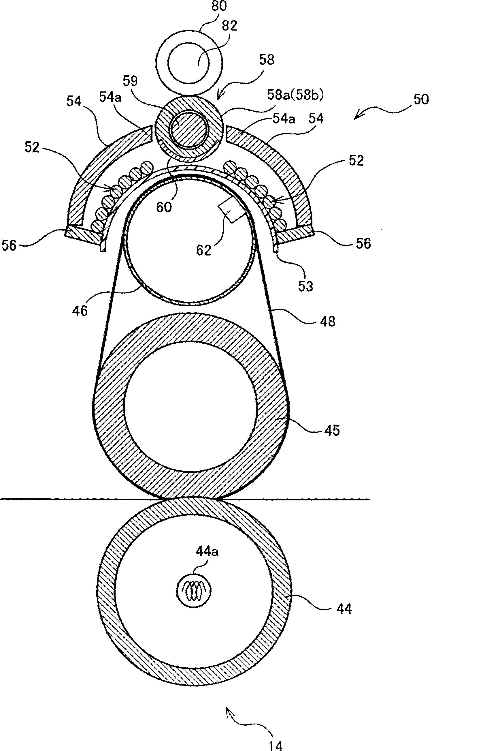
[0068] figure 2 is a longitudinal sectional view showing an example of the structure of the fixing unit 14 . exist figure 2 Middle indicates a state where the fixing unit 14 mounted on the image forming apparatus 1 is rotated about 90 degrees in the counterclockwise direction. Thus, in figure 1 The paper feed direction extending from bottom to top in figure 2 from right to left. In addition, in the case where the device main body 2 is larger (such as a digital composite machine), it may be installed as figure 2 orientation shown. In addition, there are other arrangements, for example, the fixing unit 14 is configured from figure 2 The states shown are tilted left or right poses.

[0069] The fixing unit 14 has the pressure roller 44 , the fixing roller 45 , the heating roller 46 , and the heating belt 48 as...

no. 2 approach

[0138] Details of the fixing unit

[0139] Next, the fixing unit 14 of the second embodiment used in the image forming apparatus 1 will be described in detail.

[0140] Figure 11 It is a longitudinal sectional view showing the fixing unit 14 of the second embodiment. The fixing unit 14 of the second embodiment is the same as the first embodiment, and its basic components include a pressure roller 44 , a fixing roller 45 , a heating roller 46 , and a heating belt 48 . The description of these components 44 , 45 , 46 , 48 is therefore omitted.

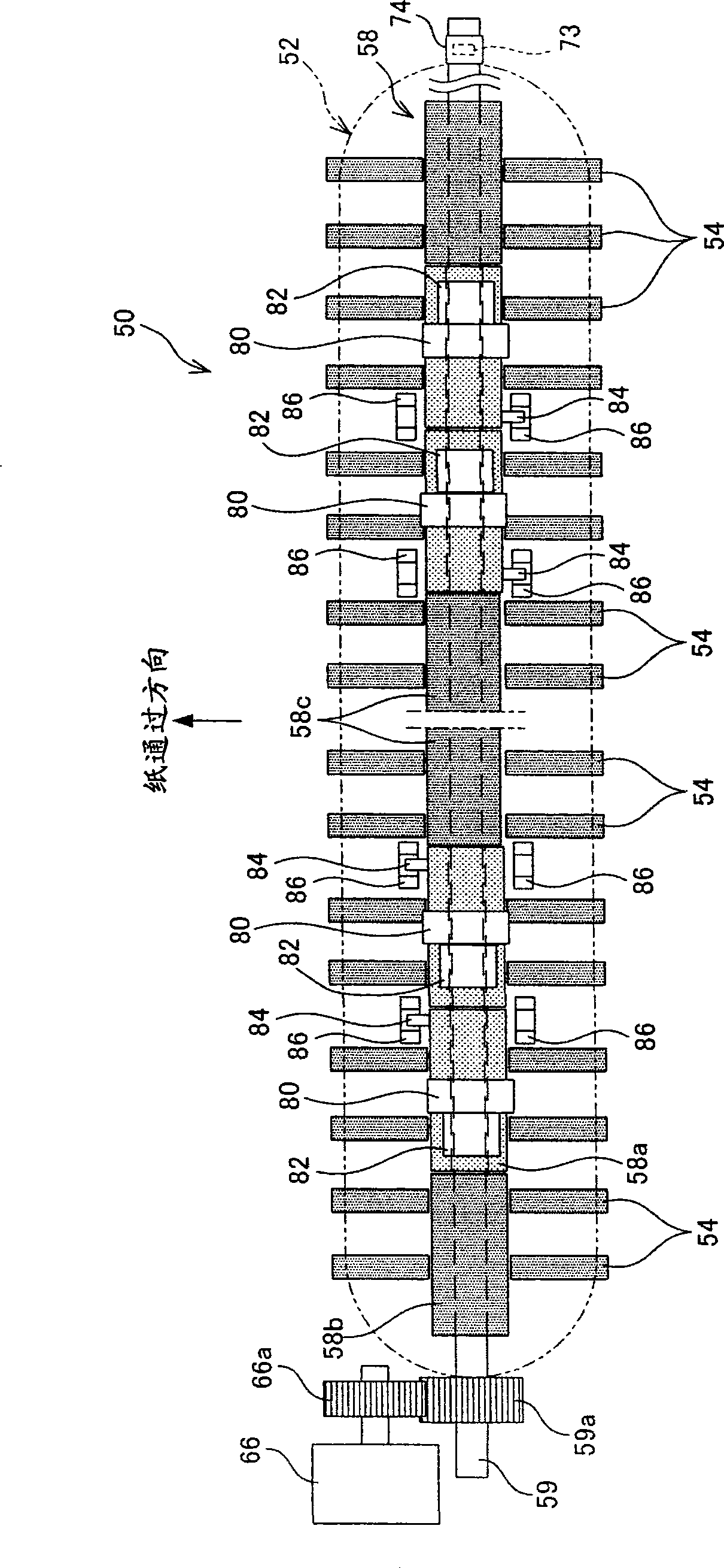
[0141] The fixing unit 14 further includes an IH coil unit 150 outside the heating roller 46 and the heating belt 48 . The IH coil unit 150 includes an induction heating coil 52 , a pair of arc cores 54 , a pair of side cores 56 , and a center core 158 . The structures of the induction heating coil 52, the arch core 54, and the side core 56 of the IH coil unit 150 are substantially the same as those of the IH coil 50 in the first ...

no. 3 approach

[0188] Figure 17is a diagram showing the fixing unit 14 of the third embodiment. In the third embodiment, the notch 90 is formed in each block core 158 a instead of the shield member 160 , so that the cross section of each block core 158 a is arcuate.

[0189] Notch

[0190] A part of the block core 158a is cut away in the axial direction to form a notch 90 . The notch 90 can also be formed at the same time by using a molding die when the ferrite powder is sintered, or it can be formed by cutting it after it is made into a cylindrical shape (cylindrical shape) (finally, the cross section can be arc-shaped) .

[0191] In the third embodiment, too, an axial groove 158c and a circumferential groove 158d are formed inside the block core 158a, and protrusions 159a, 159b, and 159c are formed on the shaft member 159. However, since the notch 90 is formed, the axial groove 158c and the circumferential groove 158d are formed avoiding the notch 90 . The rotation or non-rotation ...


PUM


Abstract

The invention provides an image forming apparatus. The image forming apparatus includes a fixing unit. The fixing unit includes a coil configured along the external surface of the heating member for generating magnetic field; a fixed core, separated from the coil at the opposite side of the heating member, for forming a magnetic path, a plurality of movable cores forming a magnetic path together with the fixed core, configured between the fixed core and the heating member on the field direction generated by the coil and arranged along the sheet conveyed region; a shielding member arranged on at least one movable core and shielding magnetism; and a magnetism adjustment unit rotating at least one movable core to switch the position of the shielding member between a shielding position where the shielding member is positioned inside the sheet conveyed region to shield the magnetism and a retracted position where the shielding member is positioned outside the sheet conveyed region to permit pass of the magnetism.

Description

technical field [0001] The present invention relates to an image forming apparatus having a fixing unit for passing a paper carrying a toner image through a nip between a pair of heating rollers or a heating belt and a roller to heat and melt unfixed toner, Fixes on paper. Background technique [0002] In recent years, from the viewpoints of shortening the warm-up time in the fixing unit and saving energy, attention has been paid to adopting a belt system capable of reducing heat capacity in image forming apparatuses (see, for example, Japanese Patent Application Laid-Open No. 6-318001). In addition, in recent years, the electromagnetic induction heating method (IH) that can heat quickly and efficiently has also attracted attention. From the perspective of energy saving during color image fixing, many products that combine the electromagnetic induction heating method and the belt method have been produced. In the case of combining the belt method and the electromagnetic ind...

Claims


Application Information

Patent Timeline
Patent Type & Authority Applications(China)
IPC IPC(8): G03G15/20G03G15/01H05B6/14
Inventor 权钟浩南条让近藤昭浩中嶋荣次石田直行笠间健一浅利珠美
Owner KYOCERA DOCUMENT SOLUTIONS INC
Why Eureka
Try Eureka