Portable IGBT arc welding machine

a technology of igbt and arc welding machine, which is applied in the direction of welding apparatus, dc-dc conversion, manufacturing tools, etc., can solve the problems of increasing the capacity of the welding machine, difficult to realize miniaturization, and inability to quickly dissipate heat, etc., to achieve low heat generation, low switching loss, and large capacity of each individual transistor

Active Publication Date: 2014-07-31
SHENZHEN JASIC TECH
View PDF50 Cites 34 Cited by
  • Summary
  • Abstract
  • Description
  • Claims
  • Application Information

AI Technical Summary

Benefits of technology

[0013]According to the present invention, the inverter circuit is formed of a commonly used full-bridge hard switching structure and insulated gate bipolar transistors G1, G3 and G2, G4 constitute bridge arms that are sequentially conducted. The IGBT is a third-generation power element, which possesses the advantages of both a field effect transistor and a giant transistor GTR and shows the advantages of large capacity of each individual transistor, low switching loss and low heat generation, increased resistance against voltage, excellent thermal stability, and being easy to drive. Due to the advantages of IGBT, the present invention does not need parallel connection of multiple transistors and thereby improves the reliability of welding machine. Also, due to low heat generation, there is no need for a large-size heat dissipater and fan, thereby effectively reducing the overall size of the machine. The high-frequency primary transformer of the present invention adopts a microcrystalline alloy ferrite core and uses high voltage and high temperature resistance insulation materials for both the primary and secondary sides so as to provide the advantages of high power density, easy heat dissipation, and easy installation. The conversion from the direct current into the alternate current is an instantaneous inversion operation in which the frequency of the alternate current is extremely high, generally as high as tens of thousands Hertz. Due to such a high frequency, the turns of winding of the primary transformer is small and the ferrite core is small, making the welding machine compact in size and light in weight, and further, the loss of the transformer is made small, leading to enhanced overall efficiency. The dual output current control type pulse width modulator chip KA3864 of the present invention adopts a peak current mode control method. The current type control method shows the following advantages: (1) It provides pulse by pulse control, having fast dynamic response, high output precision, and excellent stability (2) It provides instantaneous protection to effectively prevent over current of IGBTs. (3) It prevents bias magnetism from occurring in the high-frequency primary transformer and severe bias magnetism may cause damage of IGBTs or even the primary transformer. Through use of KA3846, the present invention improves the working reliability of the whole machine. In summary, the present invention has reliable operation, compact size, and low cost.

Problems solved by technology

The first one is that due to the constraint that a single transistor does not provide a large current, the welding machine requires multiple transistors connected in parallel, whereby the chance that the welding machine malfunctions is increased.
The second one is that due to the frequency of inversion being high, the transistor and fast recovery diode generate great heat and further due to the constraint imposed by the structure of the primary transformer, the heat cannot be quickly dissipated, whereby although frequency of inversion is high, a welding machine of the same current and same loading factor would require a much larger heat dissipater and fan, making it difficult to realize miniaturization.
The third one is that due to the factors of large number of transistors used and large size of heat dissipater and fan, the cost is increased under the same parameters.

Method used


Image

  • Portable IGBT arc welding machine
  • Portable IGBT arc welding machine
  • Portable IGBT arc welding machine

Examples


Embodiment Construction

[0022]The following descriptions are exemplary embodiments only, and are not intended to limit the scope, applicability or configuration of the invention in any way. Rather, the following description provides a convenient illustration for implementing exemplary embodiments of the invention. Various changes to the described embodiments may be made in the function and arrangement of the elements described without departing from the scope of the invention as set forth in the appended claims.

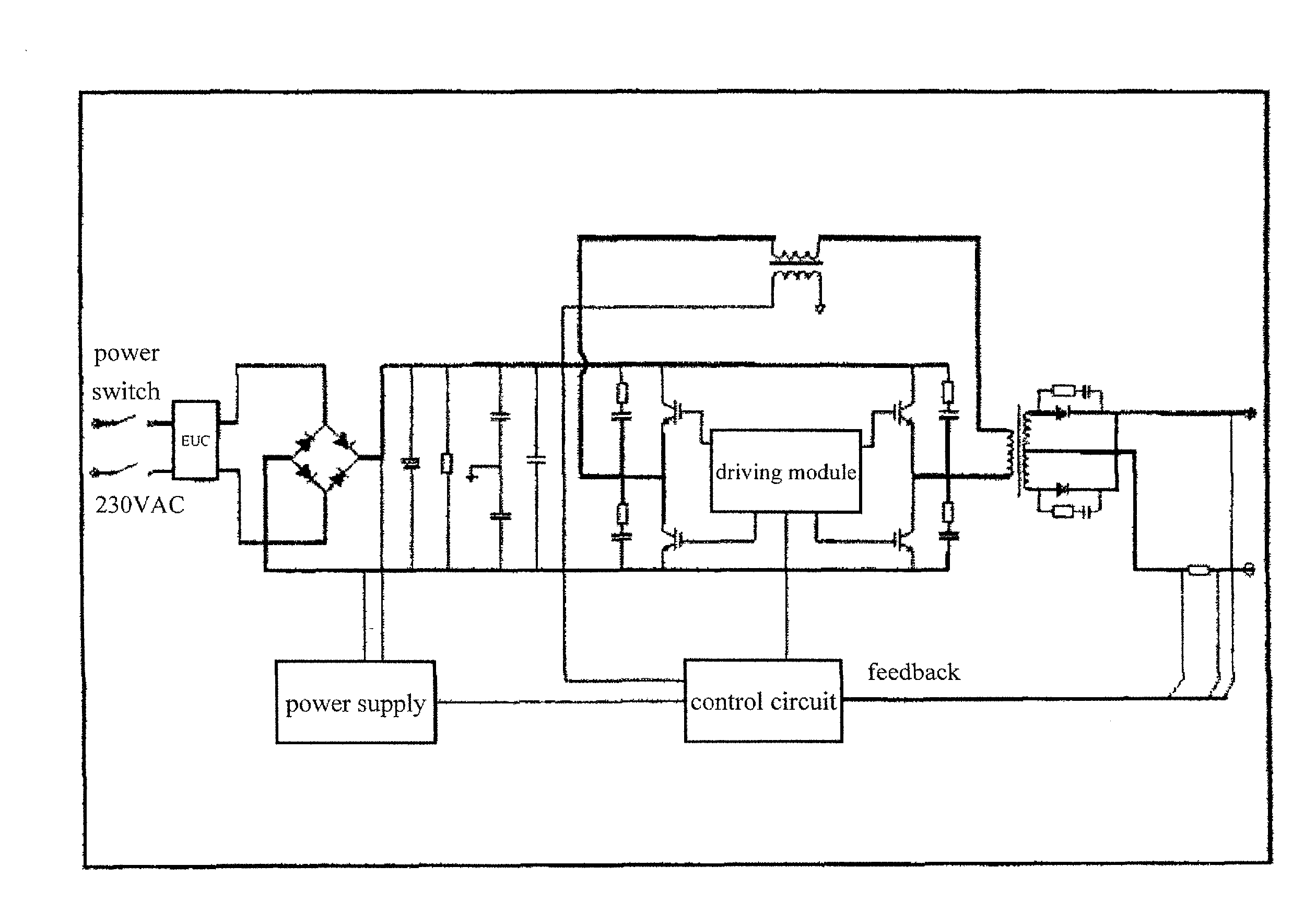
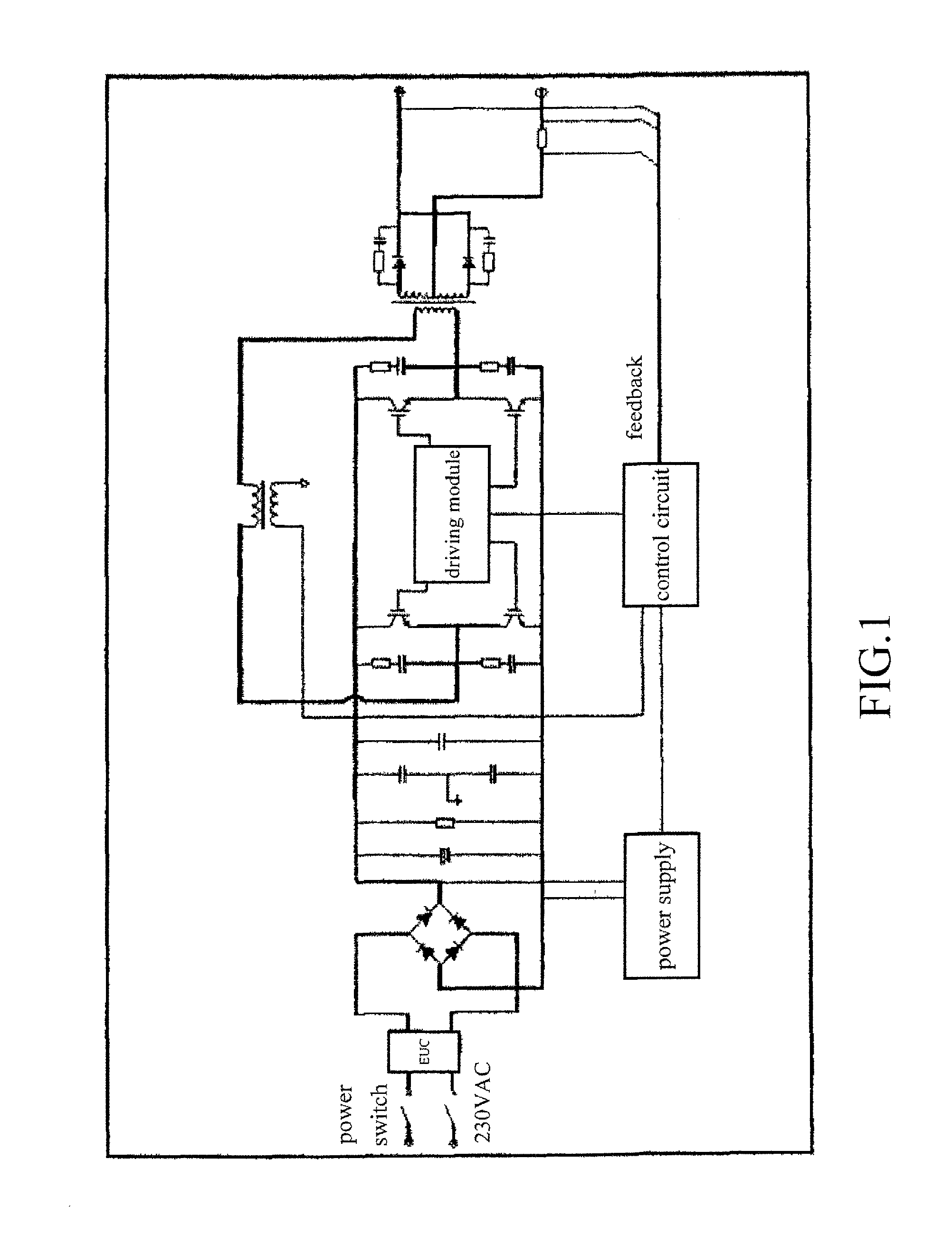
[0023]As shown in FIG. 1, the present invention provides a novel portable IGBT (Insulated Gate Bipolar Transistor) inverter arc welding machine, which comprises a main circuit to which a control circuit and an auxiliary power supply circuit are connected. In FIG. 1, the main circuit is identified as the circuitry portion other than the blocks of control circuit, driving module, and auxiliary power supply circuit. The driving module comprises an IGBT driving circuit.

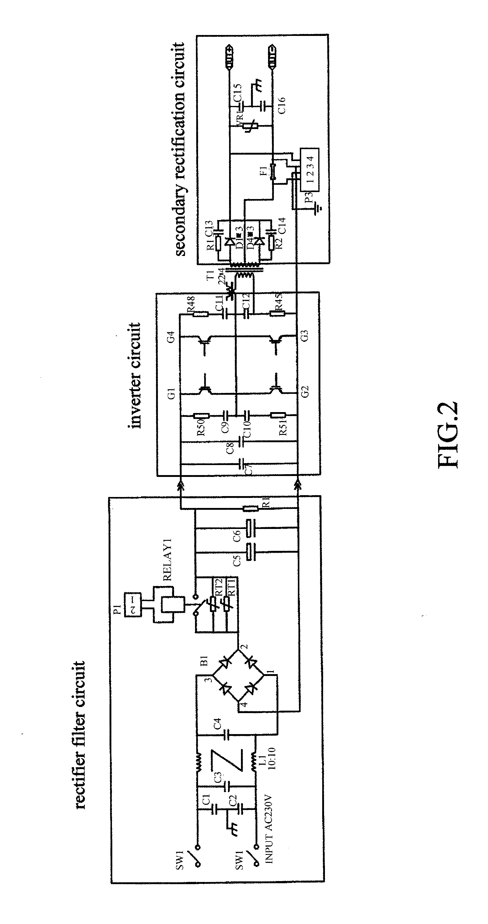
[0024]As shown in FIG. 2, the main...


PUM

PropertyMeasurementUnit
frequencyaaaaaaaaaa
temperature resistanceaaaaaaaaaa
frequencyaaaaaaaaaa

Abstract

A portable IGBT (Insulated Gate Bipolar Transistor) of high reliability, compact size, and low cost includes a main circuit to which a control circuit and an auxiliary power supply circuit are connected. The main circuit includes, in sequence, an input rectifier filter circuit, an inverter circuit, a high-frequency primary transformer, and a secondary output rectifier circuit. The control circuit includes a PWM regulation circuit, an IGBT driving circuit, a current feedback circuit, and a current setup circuit. The inverter circuit includes a full-bridge hard switching structure, which has IGBTs constituting bridge arms that are sequentially conducted, so that their alternating conduction converts direct current into high frequency square wave alternating current, which flows through the high-frequency primary transformer and is then subjected to rectification to supply an output of low voltage direct current. Each IGBT is connected in parallel to resistor and capacitor, which constitute a peak voltage absorption circuitry.

Description

(a) TECHNICAL FIELD OF THE INVENTION[0001]The present invention generally relates to an inverter arc welding machine, and more particularly to a portable IGBT (Insulated Gate Bipolar Transistor) inverter arc welding machine.(b) DESCRIPTION OF THE PRIOR ART[0002]Conventional small-sized arc welding machines often use power field effect transistor to serve as primary switching components. Consequently, the conventional inverter arc welding machine suffers the following disadvantages. The first one is that due to the constraint that a single transistor does not provide a large current, the welding machine requires multiple transistors connected in parallel, whereby the chance that the welding machine malfunctions is increased. The second one is that due to the frequency of inversion being high, the transistor and fast recovery diode generate great heat and further due to the constraint imposed by the structure of the primary transformer, the heat cannot be quickly dissipated, whereby a...

Claims


Application Information

Patent Timeline
Patent Type & Authority Applications(United States)
IPC IPC(8): B23K9/10H02M1/00
CPCB23K9/1006B23K9/091B23K9/1043H02M3/3353H02M1/007
Inventor XU, AIPINGPAN, LEIXIAO, BO
Owner SHENZHEN JASIC TECH
Why Eureka
Try Eureka