High-speed turn-milling combined machining power electric main shaft device and manufacturing method thereof

A compound processing and spindle device technology, which is applied to other manufacturing equipment/tools, positioning devices, manufacturing tools, etc., can solve the problems of increasing equipment introduction costs, equipment maintenance costs, and restricting rapid development, achieving high dynamic characteristics and reducing additional Load, the effect of ensuring the reliability of the work

Active Publication Date: 2011-01-12
通用技术集团沈阳机床有限责任公司
View PDF5 Cites 35 Cited by
  • Summary
  • Abstract
  • Description
  • Claims
  • Application Information

AI Technical Summary

Problems solved by technology

As the core technology of the turning-milling compound machining center, the power electric spindle technology of the turning-milling compound machining center has been monopolized by foreign countries, which greatly increases the cost of equipment introduction and equipment maintenance for domestic manufacturers, and restricts the rapid development of my country's automobile, military, aviation, energy and other industries. develop

Method used


Image

  • High-speed turn-milling combined machining power electric main shaft device and manufacturing method thereof
  • High-speed turn-milling combined machining power electric main shaft device and manufacturing method thereof
  • High-speed turn-milling combined machining power electric main shaft device and manufacturing method thereof

Examples


Embodiment Construction

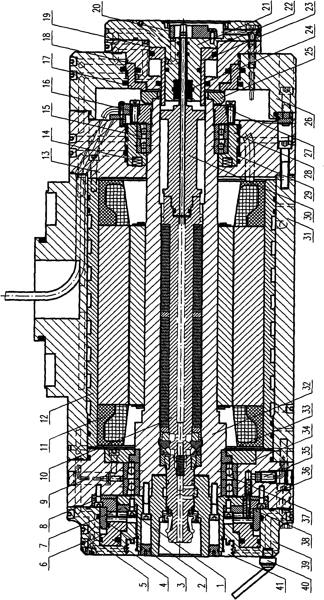
[0012] The power electric spindle device for high-speed turning-milling compound machining is installed on the high-speed five-axis turning-milling compound machining machine tool, and has supporting electrical, hydraulic and control parts correspondingly combined with the system on the machine tool, see figure 1 , which is characterized in that a water jacket 12, a built-in motor 11 and a main shaft 32 are installed concentrically in the spindle box 31 from outside to inside, a broach mechanism 10 is installed in the inner hole of the main shaft 32, and a broach sleeve 2 is installed on the front end of the broach mechanism 10, and the broach The rear end of the mechanism 10 is connected with the connecting sleeve 30 and the knife unloading mechanism; the front bearing 37 and the rear bearing 15 installed on the outer walls of the two ends of the main shaft 32 form the bearing variable preload structure respectively; a circular grating 16 is installed on the locking nut 27 at t...


PUM


Abstract

The invention relates to a high-speed turn-milling combined machining power electric main shaft device and a manufacturing method thereof. The main shaft device is arranged on a high-speed five-shaft turn-milling combined machining machine tool, and assorted electric, hydraulic and control parts are correspondingly combined with a system on the machine tool. The high-speed turn-milling combined machining power electric main shaft device is characterized in that the inside of a main shaft box is concentrically provided with a water jacket, an in-built motor and a main shaft from the outside to the inside; the inner bore of the main shaft is provided with a broach mechanism; the front end of the broach mechanism is provided with a broach case, and the rear end thereof is connected with a connecting sleeve and a broach detaching mechanism; a front bearing and a rear bearing which are arranged on the outer walls of both ends of the main shaft respectively form a bearing variable pre-tightening structure; a three-fluted disc mechanism is arranged on the periphery of the broach case; a broach oil cylinder is formed by a sleeve; an unloading oil cylinder, the broach detaching oil cylinder and a broach forging oil cylinder which are arranged at the rear end of the main shaft are arranged on the main shaft box through a rear end cover and a big flange; and an oil inlet and an oil outlet are respectively connected with the hydraulic system of the machine tool. The invention can realize the combined machining, such as high-rigidity lathe machining, high-rotating speed milling and the like.

Description

technical field [0001] The present invention relates to mechanical manufacturing equipment. Background technique [0002] The turning and milling compound machining center has the functions of turning, milling, drilling, boring, tapping, deep hole processing, turning and milling internal and external threads, etc. These functions are mainly realized by the turning and milling compound machining power spindle device, so it is required that such devices can not only install In addition to milling with rotating tools, turning tools can also be installed to realize combined turning and milling. As the core technology of the turning-milling compound machining center, the power electric spindle technology of the turning-milling compound machining center has been monopolized by foreign countries, which greatly increases the cost of equipment introduction and equipment maintenance for domestic manufacturers, and restricts the rapid development of my country's automobile, military, a...

Claims


Application Information

Patent Timeline
Patent Type & Authority Applications(China)
IPC IPC(8): B23P23/02B23B19/02B23Q3/155B23Q11/10
Inventor 王家兴盖立亚刘守胜白平徐海东李德珍赵尚福李晓峰韦峰刘志坤
Owner 通用技术集团沈阳机床有限责任公司
Why Eureka
Try Eureka