Supercharge Your Innovation With Domain-Expert AI Agents!

Electro-optical modulator bias control device and method based on Sagnac ring

An electro-optical modulator and bias voltage control technology, which is applied in the direction of instruments, optics, nonlinear optics, etc., can solve the problems of bias voltage control, DC component influence, and the inability to lock the DC operating point, etc., and achieve high-precision bias voltage control, The effect of simple algorithm and low cost

Active Publication Date: 2016-08-31
XIDIAN UNIV
View PDF2 Cites 14 Cited by
  • Summary
  • Abstract
  • Description
  • Claims
  • Application Information

AI Technical Summary

Problems solved by technology

But its main disadvantage is that the DC component is affected by the RF signal, especially when it works near the minimum operating point. When the RF signal changes, the DC component will change significantly, so that when the DC component remains unchanged, the DC cannot be locked. operating point, which affects the bias control

Method used


Image

  • Electro-optical modulator bias control device and method based on Sagnac ring
  • Electro-optical modulator bias control device and method based on Sagnac ring
  • Electro-optical modulator bias control device and method based on Sagnac ring

Examples


Embodiment Construction

[0023] The embodiments of the present invention will be described in detail below with reference to the drawings: this embodiment is implemented on the premise of the technical solution of the present invention, and detailed implementation modes and specific operation procedures are given, but the protection scope of the present invention is not limited to the following The described embodiment:

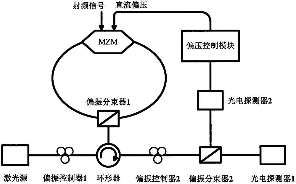
[0024] figure 1 It is a schematic diagram of the system link of the present invention using the Sagnac loop and the bias control module for bias control. Among them, the electro-optical modulator is used to modulate the intensity of the optical carrier signal; the Sagnac ring divides the optical carrier into two paths, and polarizes the optical signal modulated in the forward direction and the unmodulated optical carrier in the reverse direction for polarization multiplexing and output; the subsequent polarization controller And polarization beam splitter is used to separate the forward...


PUM


Abstract

The invention discloses a system device and method for controlling the bias voltage of an electro-optical modulator, provides an automatic bias control system based on a Sagnac ring and a direct-current power detecting algorithm and mainly relates to the field of the optical communication technology and automatic control. According to the system device and method for controlling the bias voltage of the electro-optical modulator, an optical carrier is split into two paths at the output end of a light source with a polarization controller and a polarization beam splitter and enters the Sagnac ring, wherein the clockwise optical carrier is subjected to intensity modulation, while the anticlockwise optical carrier is not modulated with radio-frequency signals due to the reverse modulation characteristic of the electro-optical modulator; optical signals output by the Sagnac ring pass through the polarization controller and the polarization beam splitter so as to make the unmodulated optical signals enter a bias control module through a photoelectric detector, judgment and compensation can be carried out on direct-current drifting with a direct-current power detection method, and thus a direct-current working point of the modulator is locked. According to the scheme, the defect that the direct-current power detection method is affected by radiofrequency signals is overcome with the Sagnac ring, and automatic bias control irrelevant to the radiofrequency signals is achieved.

Description

Technical field [0001] The present invention relates to the field of optical communication technology and automatic control, in particular to a device and method for realizing bias control of an electro-optic modulator based on a Sagnac ring. Background technique [0002] Radio over Fiber (RoF) technology uses the respective advantages of optical fiber and high-frequency radio waves to realize low-cost, large-capacity radio frequency signal optical fiber transmission and wireless access, which is an inevitable trend in the development of broadband access in the future. Electro-optical modulators based on lithium niobate materials are widely used in RoF systems because of their large modulation bandwidth, low loss, and zero chirp. Their performance plays a decisive role in the signal transmission quality of the entire system. [0003] The transfer function of the electro-optical modulator is generally a sine function. Due to the limitation of the modulation material and structure, t...

Claims


Application Information

Patent Timeline
Patent Type & Authority Applications(China)
IPC IPC(8): G02F1/03
CPCG02F1/0327
Inventor 潘豪文爱军高永胜
Owner XIDIAN UNIV
Features
  • R&D
  • Intellectual Property
  • Life Sciences
  • Materials
  • Tech Scout
  • Unparalleled Data Quality
  • Higher Quality Content
  • 60% Fewer Hallucinations
Learn More