Heat-dissipation dustproof switch cabinet

A switch cabinet and dust-proof technology, applied in the field of switch cabinets, can solve the problems of poor heat dissipation, dust entering the switch cabinet, unfavorable heat dissipation and ventilation, etc., and achieve the effect of improving dust-proof effect, convenient disassembly and cleaning, and improving heat dissipation efficiency

Inactive Publication Date: 2016-08-31
扬中市美娴电器有限公司
View PDF5 Cites 11 Cited by
  • Summary
  • Abstract
  • Description
  • Claims
  • Application Information

AI Technical Summary

Problems solved by technology

At present, the existing electric control switchgear basically has no ventilation and heat dissipation design. In order to prevent the service life and effective control rate of the components from being reduced due to the heat generated by the electric controls inside the switchgear, most of them are installed on the wall of the electric control cabinet. hole, so that the internal heat can be dissipated through the hole, but the heat dissipation effect is poor, and it is difficult to achieve a good ventilation and heat dissipation effect. Moreover, after a long time, dust will easily enter the switch cabinet and affect the service life of the electrical components in the switch cabinet. and performance, in addition, the bottom of the switchgear is mostly solid and directly falls on the ground, which is not only not conducive to heat dissipation and ventilation

Method used


Image

  • Heat-dissipation dustproof switch cabinet
  • Heat-dissipation dustproof switch cabinet
  • Heat-dissipation dustproof switch cabinet

Examples


Embodiment Construction

[0016] The following will clearly and completely describe the technical solutions in the embodiments of the present invention with reference to the accompanying drawings in the embodiments of the present invention. Obviously, the described embodiments are only some, not all, embodiments of the present invention. Based on the embodiments of the present invention, all other embodiments obtained by persons of ordinary skill in the art without making creative efforts belong to the protection scope of the present invention.

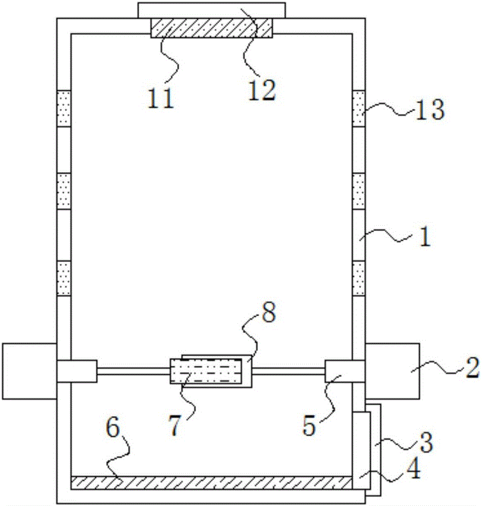
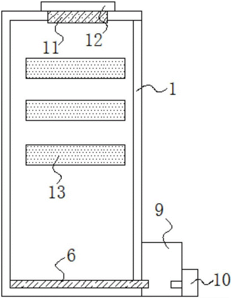
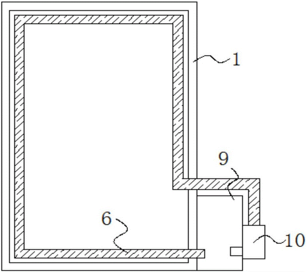
[0017] see Figure 1-3 , the present invention provides a technical solution:

[0018] A heat-dissipating and dustproof switchgear, comprising a cabinet body 1, an installation hole is opened on the top of the cabinet body 1, and a suction fan 11 is installed in the installation hole, a second dustproof cover 12 is arranged on the suction fan 11, and the cabinet body 1 There are multiple cooling holes 13 on both sides, the cooling holes 13 are rectangular hol...


PUM


Abstract

The invention discloses a heat-dissipation dustproof switch cabinet. The heat-dissipation dustproof switch cabinet comprises a cabinet body. An installation hole is formed in the top part of the cabinet body, and a suction fan is installed in the installation hole. A second dustproof cover is arranged on the suction fan. A plurality of heat dissipation holes are formed in two sides of the cabinet body, and motors are correspondingly installed on two sides of the cabinet body. The two rotors are respectively connected with a rotating shaft, the two rotating shafts are respectively and correspondingly connected with a first dust collection rod and a second dust collection rod, and the first dust collection rod and the second dust collection rod are contacted with each other. An exhaust fan is installed on an installation hole formed in the bottom part of the cabinet body. The exhaust fan is externally covered by a first dustproof cover. According to the invention, dual-heat-dissipation design is adopted, air circulation heat dissipation is formed by the exhaust and the suction fan, water circulation heat dissipation is formed by water circulation, and the heat dissipation holes formed in the cabinet body also have the heat dissipation function; in addition, the dustproof covers and the dust collection rods are used in a matching manner, so that the dustproof effect is effectively improved.

Description

technical field [0001] The invention relates to the technical field of switch cabinets, in particular to a heat dissipation and dustproof switch cabinet. Background technique [0002] Switchgear is a kind of electrical equipment, its main function is to open and close, control and protect during the process of power generation, transmission, distribution and cable conversion in the power system. At present, the existing electric control switchgear basically has no ventilation and heat dissipation design. In order to prevent the service life and effective control rate of the components from being reduced due to the heat generated by the electric controls inside the switchgear, most of them are installed on the wall of the electric control cabinet. hole, so that the internal heat can be dissipated through the hole, but the heat dissipation effect is poor, and it is difficult to achieve a good ventilation and heat dissipation effect. Moreover, after a long time, dust will easil...

Claims


Application Information

Patent Timeline
Patent Type & Authority Applications(China)
IPC IPC(8): H02B1/56H02B1/28
CPCH02B1/565H02B1/28
Inventor 施大春刘坤杨瑞峰
Owner 扬中市美娴电器有限公司
Why Eureka
Try Eureka