
Automatic rolling equipment for lead sheathes

A technology of rolling equipment and lead sleeve, applied in the field of automatic lead sleeve rolling equipment, can solve the problems of acid leakage or seepage, poor sealing effect, low production efficiency, etc.

Active Publication Date: 2016-09-07
QUANZHOU YUCRY TRAFFIC APPLIANCES
View PDF8 Cites 4 Cited by
  • Summary
  • Abstract
  • Description
  • Claims
  • Application Information

AI Technical Summary

Problems solved by technology

The lead sleeve usually needs to be provided with a sealing groove to prevent acid leakage or seepage, and the sealing groove is usually processed by turning. Although this processing method can obtain relatively high processing accuracy, due to the high accuracy requirements High turning speed is relatively slow, production efficiency is relatively low, and due to the structure of the sealing groove, the sealing effect is relatively poor, and acid may still leak or seep from the sealing groove after long-term use
[0003] Chinese invention patent application ZL201310041088.7 discloses a lead sleeve extrusion molding device. Under the action of a power mechanism (such as a press), the upper mold mechanism can move up and down to realize the opening and closing of the mold, and the lower mold mechanism has movable inserts. The lead blank is placed on the lead blank station of the movable insert assembly, and the lead blank is extruded through the cooperation of the upper mold insert and the movable insert assembly, and the sealing groove on the lead sleeve is also extruded together. Forming, although this processing method has high productivity, the sealing groove obtained by the processing is still a conventional sealing groove, and it is difficult to solve the problem that the acid may leak or seep out

Method used


Image

  • Automatic rolling equipment for lead sheathes
  • Automatic rolling equipment for lead sheathes
  • Automatic rolling equipment for lead sheathes

Examples


Embodiment Construction

[0040] The present invention will be further described below in conjunction with the accompanying drawings and specific embodiments.

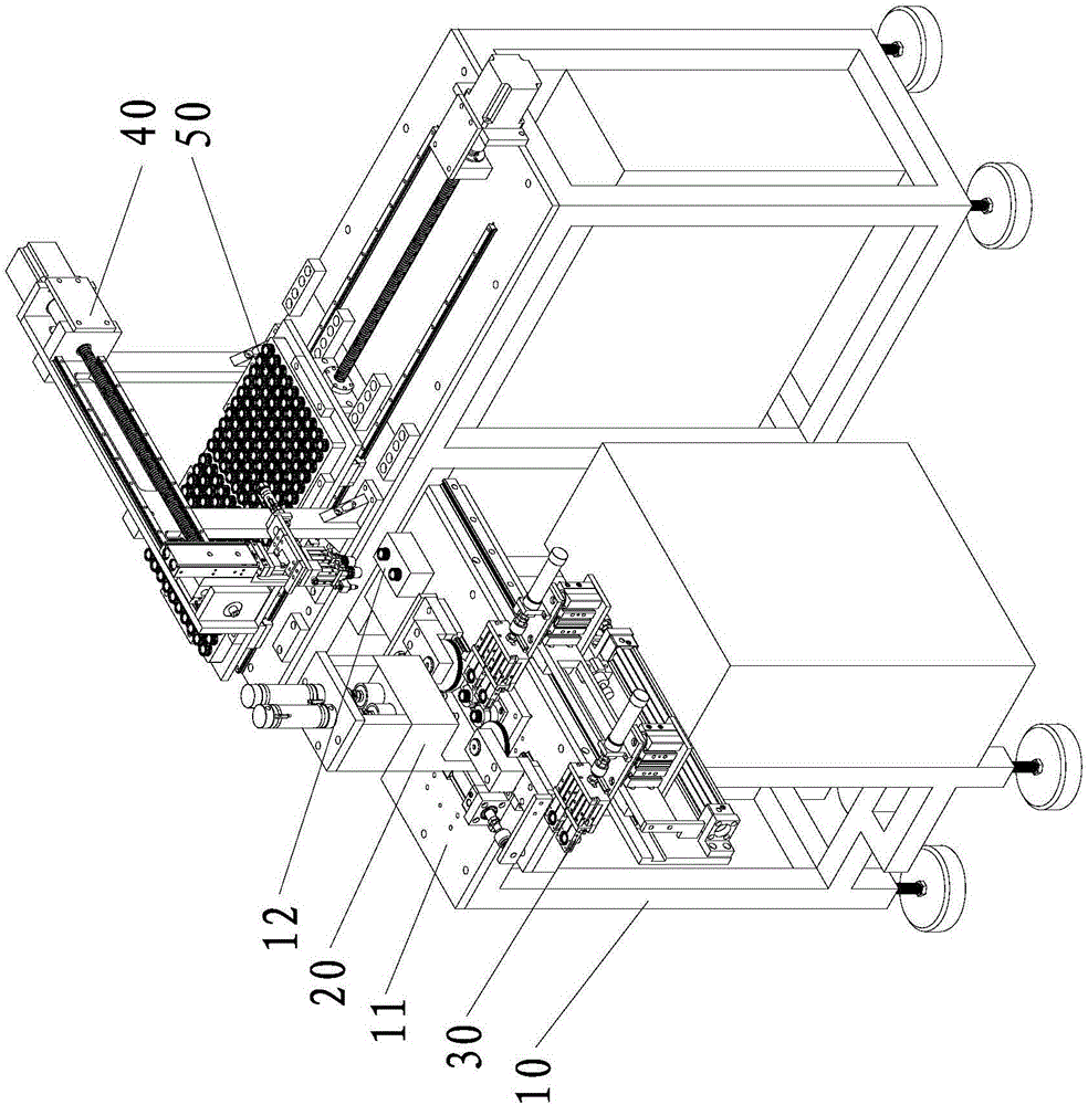
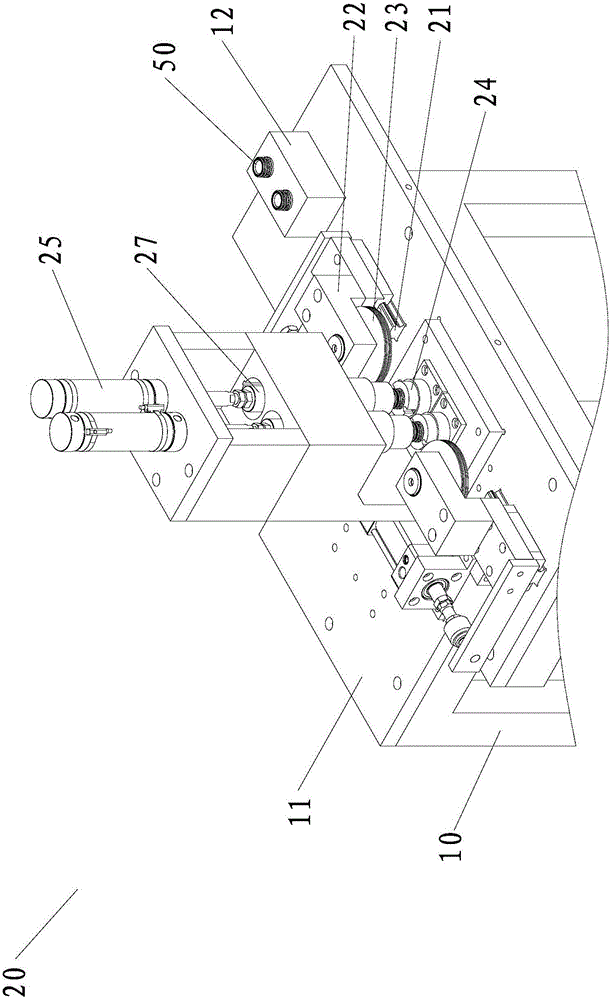
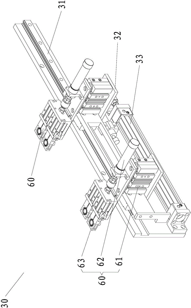
[0041] like figure 1 As shown, the lead sleeve automatic rolling equipment provided in this embodiment includes a frame 10, the frame 10 is provided with a first workbench 11, the first workbench 11 is provided with a rolling device 20, and the first workbench 11 One side is provided with a reclaimer 30 that cooperates with the rolling device 20, and the other side of the first workbench 11 is provided with a rewinder 40. It should be noted that the reclaimer 30 and the rewinder 40 do not necessarily require Located on the corresponding two sides of the first workbench 11, its specific location can be determined according to actual needs. In addition, the first workbench 11 is also provided with a storage tray 12 for placing the rolled lead sleeve 50 at a position facing the receiving device 50 .

[0042] The rolling device 20 is the core dev...


PUM


Abstract

The invention provides automatic rolling equipment for lead sheathes, which comprises a frame, wherein a first workbench is arranged on the frame; a rolling device is arranged on the first workbench; a material taking device fitted with the rolling device is arranged on one side of the first workbench; a receiving device is arranged on the other side of the first workbench; the rolling device comprises rolling guide rails, rolling wheels, rolling air cylinders, positioning sheaths, positioning air cylinders and rotary motors; and the material taking device can be used for grabbing the lead sheaths to be processed and putting the lead sheaths to be processed on the positioning sheaths, then the positioning air cylinders press the lead sheathes on the positioning sheaths tightly, meanwhile, the lead sheaths and the positioning sheaths rotate under the driving of the rotary motors, and finally, the rolling wheels press the lead sheaths under the driving of the rolling air cylinders, so that sealing grooves are formed. The automatic rolling equipment has the advantages that the production efficiency is relatively high; and a lead material, which is at the positions of the sealing grooves originally, can reel, convex rings are formed on side walls near the openings of the sealing grooves, and parts obtained after secondary injection moulding can form inverted buckle structures at the positions of the sealing grooves, so that after the obtain lead sheathes are assembled, acid liquors are prevented from leaking or exuding.

Description

technical field [0001] The invention relates to a lead sleeve processing equipment, in particular to a lead sleeve automatic rolling equipment. Background technique [0002] Lead sleeves, also known as terminals, are commonly used parts in lead-acid batteries. In the production of batteries, they are usually used as secondary injection molded inserts to connect with other parts of the battery. The lead sleeve usually needs to be provided with a sealing groove to prevent acid leakage or seepage, and the sealing groove is usually processed by turning. Although this processing method can obtain relatively high processing accuracy, due to the high accuracy requirements High turning speed leads to relatively slow turning speed, relatively low production efficiency, and due to the structure of the sealing groove, the sealing effect is relatively poor. After long-term use, acid may still leak or seep from the sealing groove. [0003] Chinese invention patent application ZL20131004...

Claims


Application Information

Patent Timeline
IPC IPC(8): B21D17/04B21D43/00B21D43/10B21D45/00B21D43/20
CPCB21D17/04B21D43/003B21D43/105B21D43/20B21D45/00
Inventor 戴增实
Owner QUANZHOU YUCRY TRAFFIC APPLIANCES
Learn More