
Drawing method and drawing mould for U-shaped drawn component

A drawing die and U-shaped technology, which is applied in the field of mechanical processing, can solve problems such as wrinkling and poor flatness of U-shaped stretched parts, and achieve the effects of simple structure, improvement of poor flatness and wrinkling, and convenient operation

Inactive Publication Date: 2016-09-07
SHENZHEN SUNWAY COMM
View PDF6 Cites 0 Cited by
  • Summary
  • Abstract
  • Description
  • Claims
  • Application Information

AI Technical Summary

Problems solved by technology

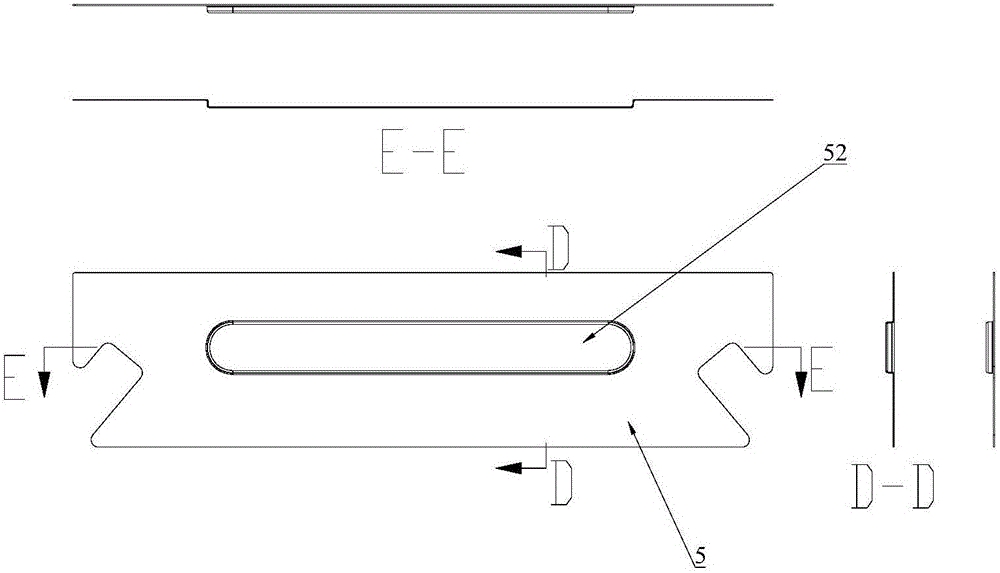
[0003] The technical problem to be solved by the present invention is to provide a simple stretching method that can effectively improve the flatness and wrinkling of U-shaped stretched parts and provide a corresponding stretching die

Method used


Image

  • Drawing method and drawing mould for U-shaped drawn component
  • Drawing method and drawing mould for U-shaped drawn component
  • Drawing method and drawing mould for U-shaped drawn component

Examples


Embodiment

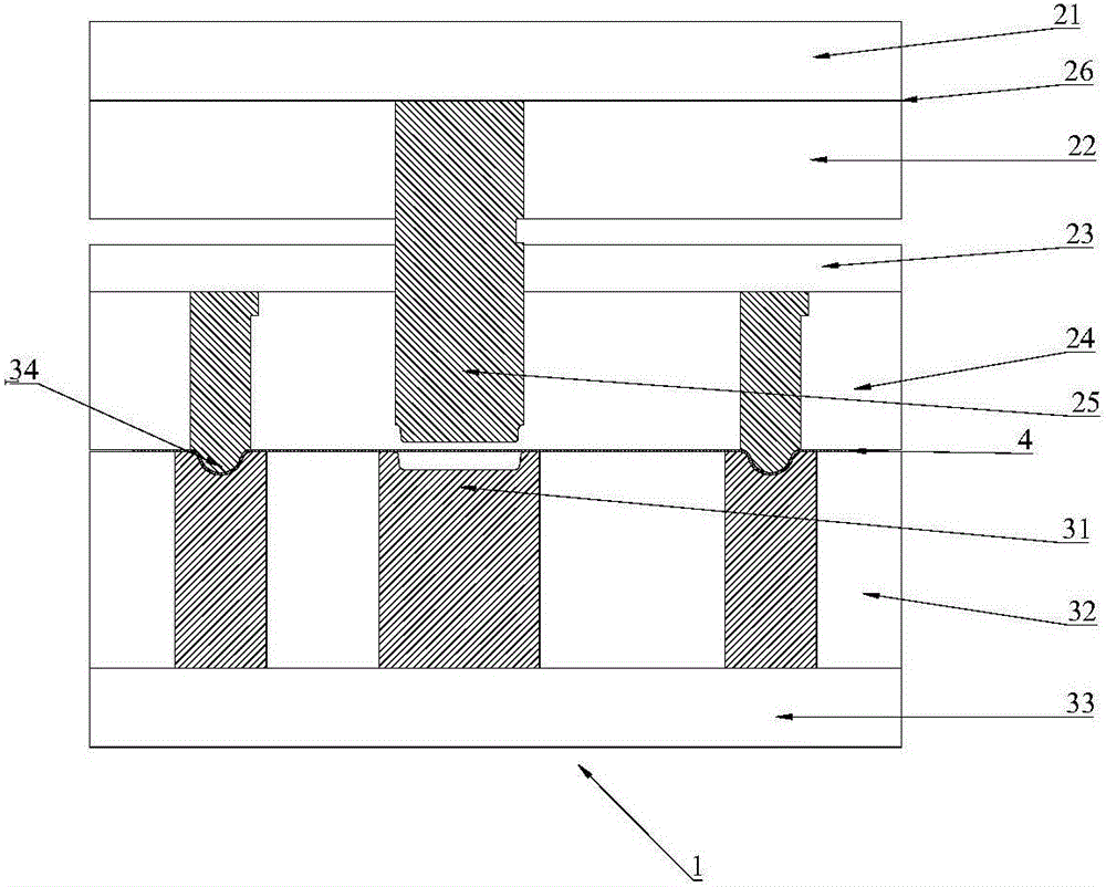
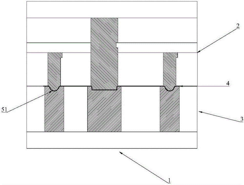
[0028] Please refer to figure 2 , a kind of drawing die 1 that can be used to form stretching part, comprises upper die part 2 and lower die part 3, and upper die part comprises punch fixing plate back plate 21, punch fixing plate 22, stripping back plate 23, The stripping plate 24, the punch 25 and the nitrogen spring 26 are composed, and the nitrogen spring is installed between the punch fixing plate back plate 21 and the punch fixing plate 22, and the stripping plate 24 and the stripping back plate 23 are provided with a The through hole, the punch 25 is located in the through hole; the stripper plate is provided with two oppositely arranged flange bumps for ribbing, and the two flange bumps are arranged on the preformed The two long sides of the stretched part, that is, the two long sides of the punch. The lower mold part includes a lower mold plate 32 and a lower mold back plate 33 , and the lower mold plate 32 is provided with a groove corresponding to the flange bump ...


PUM


Abstract

The invention discloses a drawing method for a U-shaped drawn component. During a drawing process, only two long edges of a preformed material are separately provided with pressing materials. According to the drawing method, during the drawing process, only the two long edges of the preformed material are separately provided with the pressing materials to form pressing ribs, so that phenomena of corrugation and deformation do not happen on the two ends of the drawing-moulded U-shaped drawn component; and the problems of poor flatness and corrugation of the U-shaped drawn component are effectively improved.

Description

technical field [0001] The invention relates to the technical field of mechanical processing, in particular to a U-shaped stretching method and a stretching die. Background technique [0002] At present, more and more products need to be stretched in hardware products. There are often problems of wrinkling and poor flatness in stretched parts with long U-shaped structures. In the prior art, negative gap stretching is adopted in the mold structure, nitrogen springs are added in the stretching mold to increase the material pressing force during stretching, etc., but the improvement effect is still not good, and the material flow cannot be solved well. Some positions of the tensile structure require good material flow, and some positions do not require material flow, but the existing mold structure cannot solve this problem. In the prior art, pressure ribs are also used to prevent the material from running around the edge area of ​​the product, but if figure 1 Shown is the s...

Claims


Application Information

Patent Timeline
Patent Type & Authority Applications(China)
IPC IPC(8): B21D37/10B21D22/22
CPCB21D37/10B21D22/22
Inventor 项瑞林
Owner SHENZHEN SUNWAY COMM
Learn More