
High-speed injection molding machine

An injection molding machine, high-speed technology, applied in the field of high-speed injection molding machines, can solve the problems of slow injection speed, long injection cycle, difficult to process precision products and thin products, etc., to achieve the effect of improving work efficiency and injection speed.

Inactive Publication Date: 2016-09-07
广东力劲塑机智造股份有限公司
View PDF5 Cites 2 Cited by
  • Summary
  • Abstract
  • Description
  • Claims
  • Application Information

AI Technical Summary

Problems solved by technology

Existing injection molding machines have slow injection speed and long injection cycle, making it difficult to process precision products and thin products. Therefore, the present invention provides an injection molding machine with extremely high injection speed to solve the above problems

Method used


Image

  • High-speed injection molding machine
  • High-speed injection molding machine

Examples


Embodiment Construction

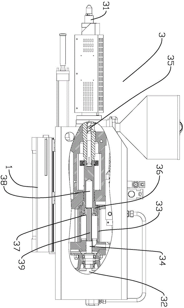
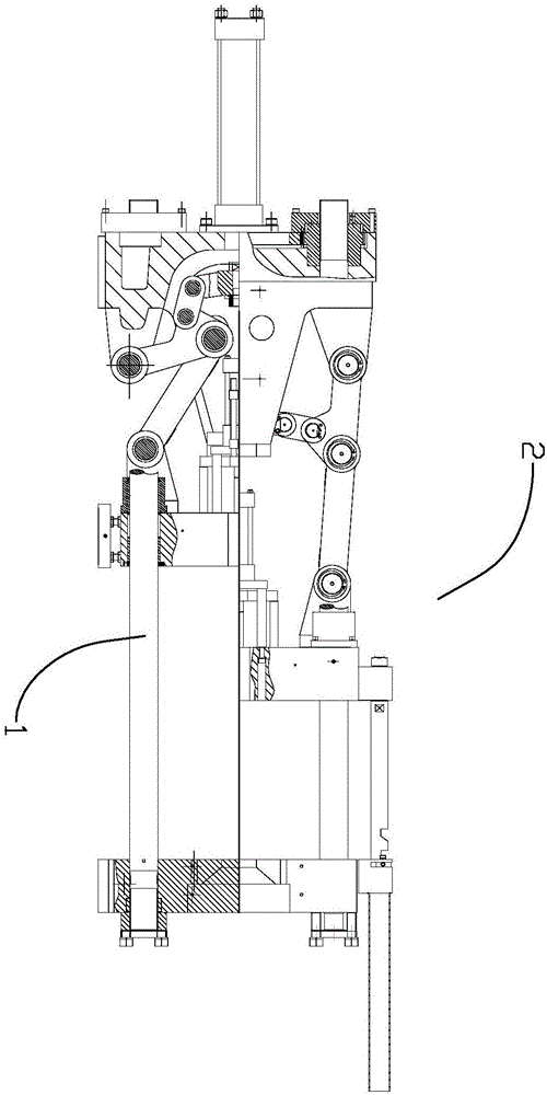
[0018] refer to Figure 1 to Figure 2 , the present invention is a high-speed injection molding machine, comprising: a frame 1; a mold clamping mechanism 2, which is arranged on the frame 1, and is used to control mold clamping and mold locking; a melt glue injection mechanism 3, which is arranged on the frame 1 It is used to inject glue into the mold; the control mechanism includes the first hydraulic pump, the second hydraulic pump and the confluence valve. The first hydraulic pump provides power for the clamping mechanism 2 through the first pipeline assembly, and the second hydraulic pump passes through the first The two pipeline components provide power for the melt glue injection mechanism, the confluence valve is connected with the first pipeline component and the second pipeline component, and can control the connection or isolation between the first pipeline component and the second pipeline component. In the present invention adopting the above-mentioned structure, t...


PUM


Abstract

The invention discloses a high-speed injection molding machine. The high-speed injection molding machine comprises a machine frame, a mold locking mechanism, a melted plastic injecting mechanism and a control mechanism, wherein the mold locking mechanism is arranged on the machine frame and used for controlling a mold to be closed and locked; the melted plastic injecting mechanism is arranged on the machine frame and used for injecting plastic into the mold; the control mechanism comprises a first hydraulic pump, a second hydraulic pump and a flow collecting valve; the first hydraulic pump supplies power to the mold locking mechanism through a first pipeline assembly, and the second hydraulic pump supplies power to the melted plastic injecting mechanism through a second pipeline assembly; and the flow collecting valve is connected with the first pipeline assembly and the second pipeline assembly and can control the first pipeline assembly to communicate or not to communicate with the second pipeline assembly. By means of the structure, the first hydraulic pump, the second hydraulic pump and the flow collecting valve are arranged on the high-speed injection molding machine, and after the processes of mold closing and locking are completed, the first pipeline assembly communicates with the second pipeline assembly through the flow collecting valve; and the power supplied by the first hydraulic pump is made to act on the melted plastic injecting mechanism, the first hydraulic pump and the second hydraulic pump supply power to plastic injecting together, and high-speed plastic injecting is achieved.

Description

technical field [0001] The invention relates to a high-speed injection molding machine. Background technique [0002] Injection molding machine is a main molding equipment for making thermoplastics or thermosetting plastics into various shapes of plastic products with plastic molding molds. It has a wide range of applications. Existing injection molding machines have slow injection speed and long injection cycle, making it difficult to process precision products and thin products. Therefore, the present invention provides an injection molding machine with extremely high injection speed to solve the above problems. Contents of the invention [0003] In order to solve the above problems, the present invention provides a high-speed injection molding machine. [0004] The technical scheme adopted by the present invention to solve its technical problems is: [0005] A high-speed injection molding machine comprising: [0006] frame; [0007] The clamping mechanism is set on ...

Claims


Application Information

Patent Timeline
IPC IPC(8): B29C45/67B29C45/70B29C45/82
CPCB29C45/67B29C45/70B29C45/82B29C2945/76869B29C2945/76896
Inventor 刘子云
Owner 广东力劲塑机智造股份有限公司
Learn More