A casting mold with an h-shaped sprue cup

A casting mold and sprue cup technology, which is applied in the field of casting molds, can solve problems such as cold shut and uneven hardness, slow pouring speed, and reduced space available for templates, so as to increase the number of products arranged in a single mold and increase the pouring speed. Improve and eliminate the effect of cold insulation defects

Active Publication Date: 2017-06-06
乔治费歇尔金属成型科技(昆山)有限公司
View PDF6 Cites 0 Cited by
  • Summary
  • Abstract
  • Description
  • Claims
  • Application Information

AI Technical Summary

Problems solved by technology

[0003] In addition to the system cycle time, the module can be produced between 80-100 modules per hour, and the appearance of these products has more sand / slag holes, cold shut and uneven hardness. Due to the current conical The pouring speed of the shaped sprue cup is slow and the molten iron flow is long, which leads to the following problems:
[0004] 1. Low production efficiency, only 80-100 molds can be produced per hour
[0005] 2. Since there is only one sprue cup, additional space is needed on the formwork to arrange the flow path in order to introduce molten iron into the cavity, which reduces the available space of the formwork and reduces the yield and production efficiency
[0006] 3. Due to the small sprue cup, the slag / sand in the molten iron does not have enough time to float up, so the sand / slag is brought into the product, causing more appearance defects and defective products after processing
[0007] 4. Due to the inconsistency of the direct molten iron flow of each cavity, the temperature of each cavity is inconsistent, so the hardness difference between each cavity after solidification is large, even beyond the technical level.

Method used


Image

  • A casting mold with an h-shaped sprue cup
  • A casting mold with an h-shaped sprue cup
  • A casting mold with an h-shaped sprue cup

Examples


Embodiment Construction

[0020] The present invention will be further described below in conjunction with the accompanying drawings.

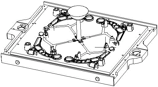
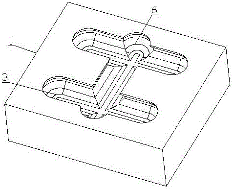
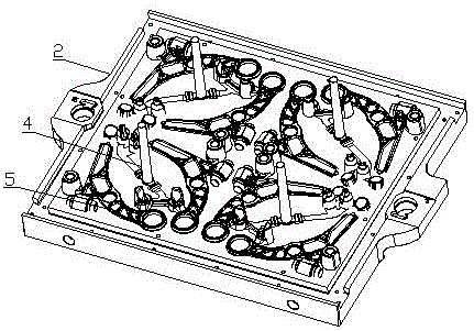
[0021] As shown in the figure, a casting mold with an H-shaped sprue cup includes an upper mold 1, a lower mold 2 and a sprue cup 3, the sprue cup is located on the upper mold, and the sprue cup has an H-shaped outer runner , there are four inner runners 4 symmetrically arranged under the H-shaped outer runner, and two connected casting cavities 5 are connected to the bottom of each inner runner. There are 4 groups of 8 casting cavities in total. The cavities of each group of castings are not connected to each other, which greatly increases the number of parts that can be arranged. The two casting cavities connected by each inner runner are arranged at 180 degrees in the horizontal direction to ensure that the two cast parts are as far as possible Consistent, with good interchangeability, the H-shaped outer flow channel is a smooth groove-shaped flow channel, which is ...


PUM


Abstract

A casting mold with an H-shaped pouring cup comprises an upper mold body, a lower mold body and the pouring cup. The pouring cup is arranged on the upper mold body and provided with an outer H-shaped flow channel. Four inner flow channels are symmetrically arranged below the outer H-shaped flow channel. Two casting cavities which are communicated with each other are connected with the bottom of each inner flow channel, namely eight casting cavities in four sets are provided. The sets of casting cavities in the casting mold are not communicated with one another. The two casting cavities connected with each inner flow channel form a 180-degree included angle in the horizontal direction. The outer H-shaped flow channel is a smooth groovy flow channel. Protruding molten metal injection positions are arranged on the two sides of the outer H-shaped flow channel. The casting mold can contain molten iron as much as 200 kg, the pouring speed is improved, the number of produced molds per hour is increased, and the number of products distributed on each mold is increased; sufficient floating time is provided for sand / slag in the molten iron, and the occurrence rate of sand / slag hole defects in products is reduced; the temperature difference between all mold cavities after pouring is reduced, and the cold shut defect of finished products is overcome.

Description

technical field [0001] The invention relates to a casting mold with a new type of sprue cup, especially the working requirement that small casting parts need to be mass-produced quickly. Background technique [0002] The gating system used in the current product production has only one conical sprue cup. When pouring, the entire sand mold can only enter the molten iron from one flow channel, and the molten iron is introduced into the mold through the flow path connecting each cavity. The current sprue cup is The weight of molten iron that can be accommodated is about 8Kg, and the fastest pouring speed of the pouring machine can reach about 50Kg / S, so the filling time depends on the current sprue cup, and the current sprue cup generally takes 25-35S to be filled. [0003] In addition to the system cycle time, the module can be produced between 80-100 modules per hour, and the appearance of these products has more sand / slag holes, cold shut and uneven hardness. Due to the curr...

Claims


Application Information

Patent Timeline
Patent Type & Authority Patents(China)
IPC IPC(8): B22C9/08
Inventor 侯继康
Owner 乔治费歇尔金属成型科技(昆山)有限公司
Why Eureka
Try Eureka