Lateral glue injection device of injection molding machine

An injection molding machine, side-mounted technology, which is applied to the field of the injection device of the side-mounted injection molding machine, can solve the problems of shortening the service life and wear of components, and achieves the effect of reducing the length of the device, reducing the manufacturing cost and wide application range.

Pending Publication Date: 2022-02-18
余姚市鹰图机械设备有限公司
View PDF0 Cites 0 Cited by
  • Summary
  • Abstract
  • Description
  • Claims
  • Application Information

AI Technical Summary

Problems solved by technology

[0005] The object of the present invention is to provide a side-mounted injection molding machine injection device to solve the disadvantages of the prior art that the single cylinder injection device is mostly placed at the tail of the propulsion cylinder. The problem is that it directly drives the piston rod of the propulsion cylinder to rotate, and transmits the rotational force to the injection screw, which causes considerable wear and tear on the seal of the piston rod of the propulsion cylinder due to rotation, greatly shortening the service life of each component

Method used


Image

  • Lateral glue injection device of injection molding machine
  • Lateral glue injection device of injection molding machine
  • Lateral glue injection device of injection molding machine

Examples


Embodiment

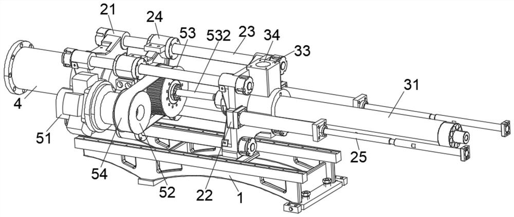
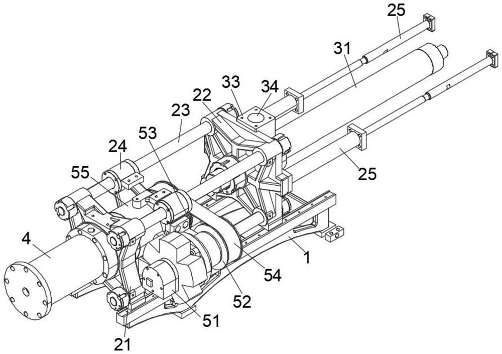
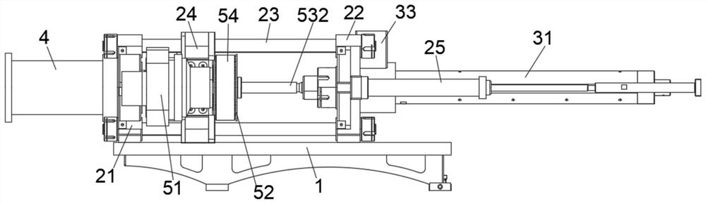
[0026] see Figure 1-5 As shown, the present invention provides a technical solution of a side-mounted injection molding machine injection device: including a base 1, the base 1 is respectively provided with a first fixed seat 21 and a second fixed seat 22, and the first fixed seat 21 and the second fixed seat 22 is connected with a positioning rod 23, the positioning rod 23 is covered with a movable bracket 24, and the movable bracket 24 is provided with a transmission mechanism. Specifically, the transmission mechanism is used to realize the rotary feeding of the injection screw rod 532. The driving part 51 on the side of the support 24, specifically, the driving part 51 can be a hydraulic motor or an electric motor, the output end of the driving part 51 is connected with a driving pulley 52, and the position of the movable support 24 is provided with a connecting seat 55, and inside the connecting seat 55 A bearing 56 is embedded, and a transmission shaft 531 is inserted in...


PUM


Abstract

The invention relates to the technical field of injection molding machine glue injection, and discloses a lateral glue injection device of an injection molding machine which comprises a base, a first fixing seat and a second fixing seat are arranged on the base, a positioning rod is connected between the first fixing seat and the second fixing seat, a movable support is arranged on the positioning rod in a sleeving mode, and a transmission mechanism is arranged on the movable support. A driving part drives the driving belt wheel to rotate, the driving belt wheel and the driven belt wheel are in transmission through a belt, namely, the driven belt wheel is driven to rotate, the injection screw rod rotates at a high speed, glue injection and injection operation of materials in the material storage barrel is completed, the driving part is designed in a side mode, the length of the device can be effectively reduced, and occupied space is reduced. Whole machine equipment is more attractive, driving belt wheels of different sizes can be replaced according to requirements, namely the speed ratio is changed by changing the size of the belt wheel of the power output part, the problem that the speed ratio is inconvenient to change in the center of the screw rod is solved, and the scheme is novel in structure, easy and convenient to operate and wide in application range and meets use requirements.

Description

technical field [0001] The invention relates to the technical field of glue injection for injection molding machines, in particular to a side-mounted glue injection device for injection molding machines. Background technique [0002] Injection molding machine, also known as injection molding machine or injection machine, is the main molding equipment for making thermoplastics or thermosetting plastics into various shapes of plastic products with plastic molding molds. It is divided into vertical, horizontal, and all-electric types. The injection molding function The plastic is heated and high pressure is applied to the molten plastic, causing it to shoot out and fill the mold cavity. [0003] The injection system is one of the most important components of the injection molding machine. Generally, there are three main forms: plunger type, screw type, and screw pre-molded plunger injection type. At present, the most widely used is the screw type. In one cycle of the machine, ...

Claims


Application Information

Patent Timeline
Patent Type & Authority Applications(China)
IPC IPC(8): B29C45/54B29C45/47B29C45/77B29C45/17
CPCB29C45/54B29C45/47B29C45/77B29C45/17
Inventor 唐亮亮
Owner 余姚市鹰图机械设备有限公司
Why Eureka
Try Eureka