Rail vehicle fairings and rail vehicles

A technology for rail vehicles and shrouds, applied in railway car bodies, railway car body components, climate sustainability, etc., can solve problems such as increased pressure differential resistance, large pressure differential resistance, aerodynamic noise, and air flow disturbance. , to achieve the effect of reducing air resistance, reducing aerodynamic noise, and avoiding turbulent air flow

Active Publication Date: 2019-01-25
CRRC TANGSHAN CO LTD
View PDF4 Cites 0 Cited by
  • Summary
  • Abstract
  • Description
  • Claims
  • Application Information

AI Technical Summary

Problems solved by technology

However, due to the positive pressure area generated on the windward side of the air-conditioning unit cowl and the pantograph cowl, and there is a gap between the air-conditioning unit cowl and the pantograph cowl, the air-conditioning unit cowl and the pantograph The air flow in the gap between the pantograph shrouds is turbulent, and the pressure difference resistance increases, resulting in greater pressure difference resistance and aerodynamic noise

Method used


Image

  • Rail vehicle fairings and rail vehicles
  • Rail vehicle fairings and rail vehicles
  • Rail vehicle fairings and rail vehicles

Examples


Embodiment Construction

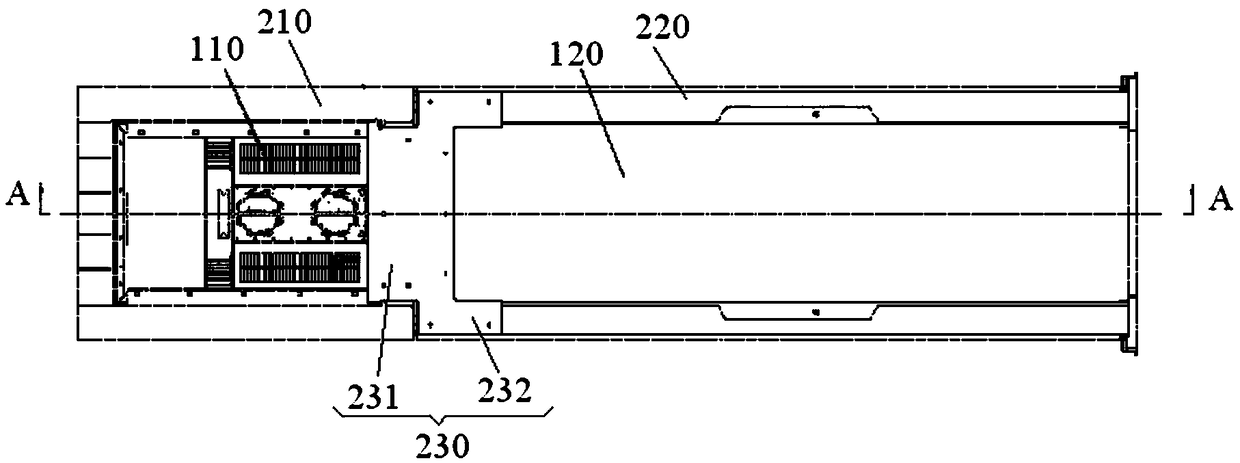
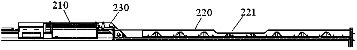
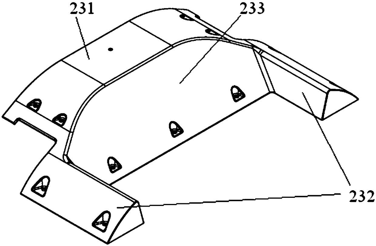
[0026] Some embodiments of the present invention will be described in detail below in conjunction with the accompanying drawings. In the case of no conflict, the following embodiments and features in the embodiments can be combined with each other.

[0027] Among them, the terms "upper", "lower", "left", "right", etc. are used to describe the relative positional relationship of each structure in the drawings, which are only for the convenience of description, and are not used to limit the present invention. The practicable scope, the change or adjustment of its relative relationship, without any substantial change in the technical content, shall also be regarded as the practicable scope of the present invention.

[0028] It should be noted that, in the description of the present invention, the terms "first" and "second" are only used to describe different components conveniently, and should not be understood as indicating or implying a sequence relationship, relative importanc...


PUM


Abstract

The invention provides an airflow guiding hood for a railway vehicle and the railway vehicle, and relates to the technology of vehicle roof airflow guiding hoods for railway vehicles. The airflow guiding hood for the railway vehicle comprises a first airflow guiding hood and a second airflow guiding hood, wherein the first airflow guiding hood is mounted in an air conditioning unit area; the second airflow guiding hood is mounted in a pantograph area; the first airflow guiding hood is connected with the second airflow guiding hood through a connecting piece; the connecting piece comprises a first connecting end and a second connecting end, wherein the first connecting end is connected with the first airflow guiding hood, and the second connecting end is connected with the second airflow guiding hood, so that the first airflow guiding hood is in smooth transition connection with the second airflow guiding hood through the connecting piece. The railway vehicle comprises the airflow guiding hood for the railway vehicle. The first airflow guiding hood is in smooth transition connection with the second airflow guiding hood through the connecting piece, so that the smooth transition of the air conditioning unit area and the pantograph area is realized; the air between the air conditioning unit area and the pantograph area has a function of guiding, so that the air resistance at the top of the vehicle body of the railway vehicle is reduced, and aerodynamic noises at the top of the vehicle body of the railway vehicle is reduced.

Description

technical field [0001] The invention relates to the technology of a rail vehicle roof deflector, in particular to a rail vehicle deflector and a rail vehicle. Background technique [0002] The top of the car body of a rail vehicle is usually equipped with an air conditioning unit and a pantograph. When the rail vehicle is running at high speed, the air conditioning unit and pantograph on the top of the car body will be in contact with the air, thereby generating resistance, which is not conducive to the high-speed operation of the rail vehicle. [0003] In the prior art, air-conditioning unit shrouds are usually installed on the air-conditioning units, and pantograph shrouds are installed on the pantographs. However, due to the positive pressure area generated on the windward side of the air-conditioning unit cowl and the pantograph cowl, and there is a gap between the air-conditioning unit cowl and the pantograph cowl, the air-conditioning unit cowl and the pantograph The ...

Claims


Application Information

Patent Timeline
Patent Type & Authority Patents(China)
IPC IPC(8): B61D17/02
CPCB61D17/02Y02T30/00
Inventor 韩璐李良杰孔繁冰管全梅孙术娟王力王赵美李国清
Owner CRRC TANGSHAN CO LTD
Why Eureka
Try Eureka