Inner winding machine clamping wire arrangement mechanism and its method

An inner winding machine and wire clamping technology, which is used in electromechanical devices, manufacturing motor generators, electrical components, etc., can solve the problems of reducing motor performance, entanglement of enameled wires, and high product defect rate, so as to avoid crushing.

Active Publication Date: 2018-11-02
东莞拓蓝自动化科技有限公司
View PDF4 Cites 0 Cited by
  • Summary
  • Abstract
  • Description
  • Claims
  • Application Information

AI Technical Summary

Problems solved by technology

[0002] At present, the items to be worked on the market are roughly divided into outer-wound and inner-wound. At present, the production of inner-wound items is basically done manually or semi-automatically. Among them, the wire process of the semi-automated inner-wound machine still uses The most important thing is to manually introduce the enameled wire into the inner winding groove. The introduction process depends entirely on the proficiency of the workers. When manually introducing enameled wires into multiple enameled wires at the same time, problems such as mutual winding of enameled wires often occur, thereby reducing the performance of the motor and the quality of the product. The product rate is also more

Method used


Image

  • Inner winding machine clamping wire arrangement mechanism and its method
  • Inner winding machine clamping wire arrangement mechanism and its method
  • Inner winding machine clamping wire arrangement mechanism and its method

Examples


Embodiment Construction

[0019] The specific implementation manners of the present invention will be described in detail below in conjunction with the accompanying drawings. Apparently, the described embodiments are only part of the embodiments of the present invention, and other embodiments obtained by those skilled in the art without creative efforts all belong to the protection scope of the present invention.

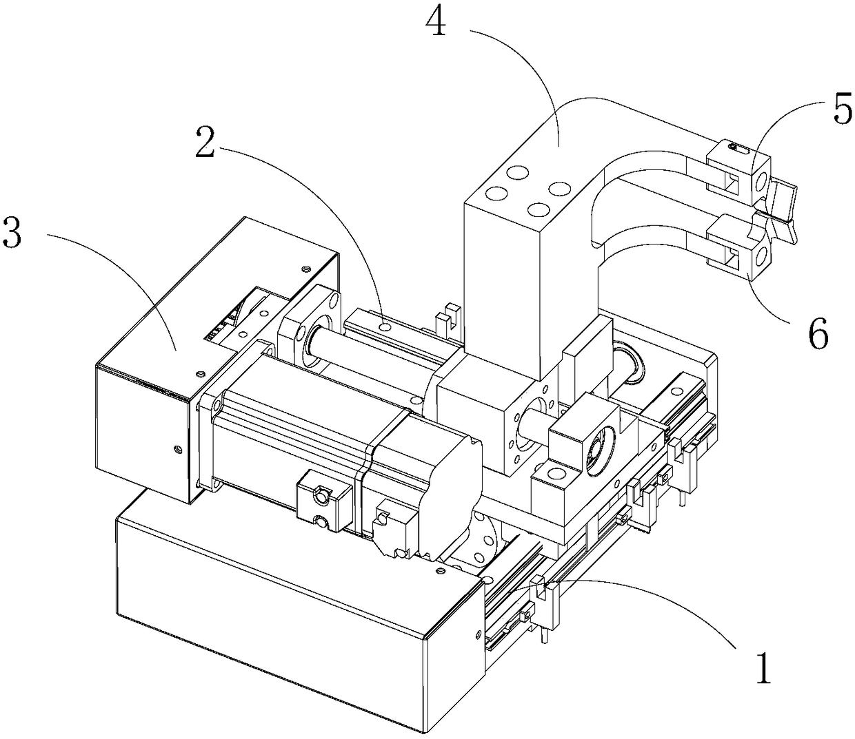
[0020] Such as figure 1 The wire clamping and arranging mechanism of the inner winding machine shown in the present invention is mainly composed of a clamping assembly and a transmission assembly. The transmission assembly includes a Y-axis longitudinal movement mechanism 1 that can move longitudinally along the longitudinal position of the article to be worked. An X-axis support 2 is provided on the axis longitudinal movement mechanism 1, and an X-axis traverse mechanism 3 that can move along the lateral position of the object to be worked is fixed on the X-axis support 2. The clamping asse...


PUM


Abstract

The invention discloses a wire arranging mechanism for wire locking of an internal winding machine and a wire arranging method. The wire arranging mechanism is mainly composed of a wire locking assembly and a transmission assembly. The transmission assembly contains one Y-axis longitudinal moving mechanism which may move longitudinally along a longitudinal position of an article to be processed. The Y-axis longitudinal moving mechanism is provided with one X-axis support thereon. The one X-axis transverse moving mechanism which may move transversly along a transverse position of the article to be processed is fixed to the X-axis support. The wire locking assembly includes a wire locking support which is arranged on the X-axis transverse moving mechanism. A front segment of the wire locking support has a bifurcated structure. An upper branch end point and a lower branch end point of the bifurcated structure are respectively provided with an upper locking block group and a lower locking block group which form a gap slit which corresponds to an in wire duct of the article to be processed. According to the invention, the wire arranging mechanism for wire locking of the internal winding machine and the wire arranging method can automatically arrange wires, automatically hang wires, and automatically adjust tensioning of enameled wires of the mechanism.

Description

technical field [0001] The invention relates to a functional component of an inner winding machine, in particular to a wire clamping and arranging mechanism of an inner winding machine and a wire arranging method thereof. Background technique [0002] At present, the items to be worked on the market are roughly divided into outer winding type and inner winding type. At present, the production of inner winding type waiting for work is basically done manually or semi-automatically. Among them, the wire process of the semi-automated inner winding machine is still used. The most important thing is to manually introduce the enameled wire into the inner winding groove. The introduction process depends entirely on the proficiency of the workers. When manually introducing enameled wires into multiple enameled wires at the same time, problems such as mutual winding of enameled wires often occur, which reduces the performance of the motor and the product. The product rate is also more...

Claims


Application Information

Patent Timeline
Patent Type & Authority Patents(China)
IPC IPC(8): H02K15/085
CPCH02K15/085
Inventor 刘发源
Owner 东莞拓蓝自动化科技有限公司
Why Eureka
Try Eureka