Aerosol-generating system having a fluid-permeable heater assembly

An aerosol generation and heater technology, applied in heating elements, heating element materials, ohmic resistance heating parts, etc., can solve the problems of fragile electrical connections, difficult to manufacture in a low-cost and repeatable manner, and difficult to dispose of. , to achieve the effect of simple connection and reliable connection

Active Publication Date: 2016-09-07
PHILIP MORRIS PROD SA
View PDF8 Cites 9 Cited by
  • Summary
  • Abstract
  • Description
  • Claims
  • Application Information

AI Technical Summary

Problems solved by technology

[0003] This type of system is efficient at generating aerosols, but is difficult to manufacture in a cost-effective and reproducible manner
and core and coil assemblies and associated electrical connections can be fragile and difficult to dispose of

Method used


Image

  • Aerosol-generating system having a fluid-permeable heater assembly
  • Aerosol-generating system having a fluid-permeable heater assembly
  • Aerosol-generating system having a fluid-permeable heater assembly

Examples


Embodiment Construction

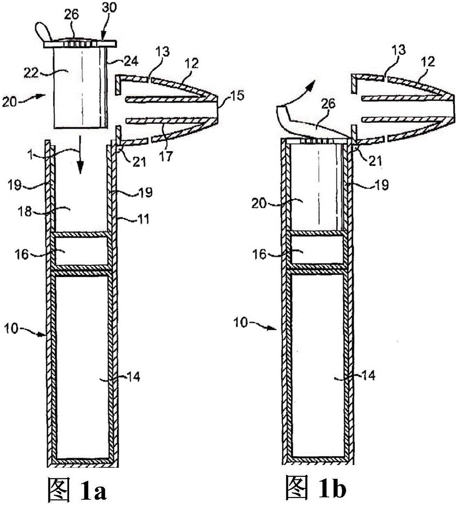
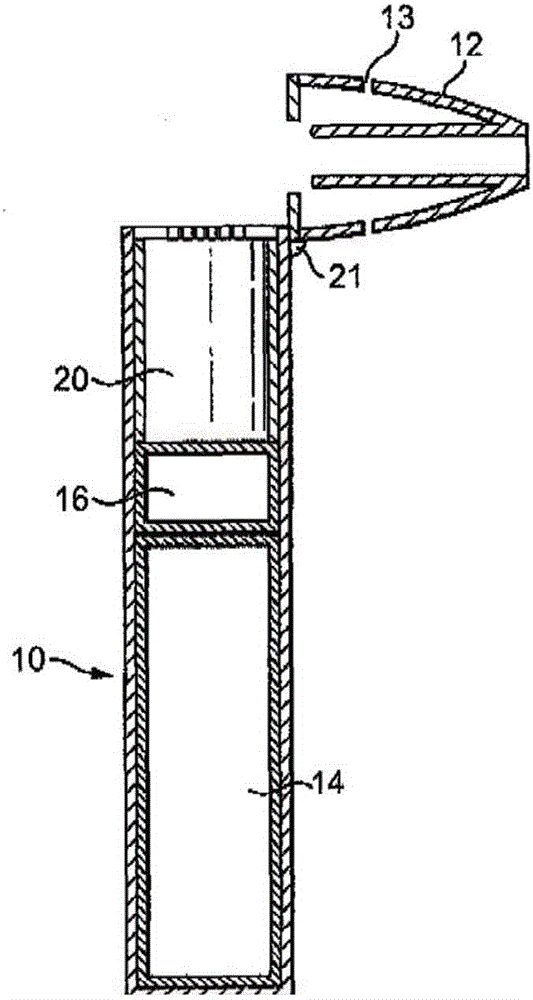
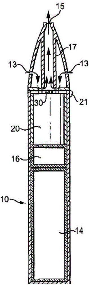
[0067] Figures 1a to 1d is a schematic diagram of an aerosol generating system comprising a cartridge according to an embodiment of the invention. Figure 1a It is a schematic diagram of the aerosol generating device 10 and the separating cartridge 20 forming the aerosol generating system together. In this example, the aerosol generating system is an electrically operated smoking system.

[0068] Cartridge 20 contains an aerosol-forming substrate and is configured to be received within cavity 18 within the device. When the aerosol-forming substrate provided in the cartridge 20 is exhausted, the cartridge should be replaceable by the user. Figure 1a Cartridge 20 is shown prior to insertion into the device, wherein Figure 1a Arrow 1 in indicates the direction of cartridge insertion.

[0069] The aerosol-generating device 10 may be a smoking device and may be of comparable size to a conventional cigar or cigarette. The device 10 comprises a body 11 and a mouthpiece portion...


PUM


Abstract

An aerosol-generating system comprises a fluid-permeable electric heater assembly (30) The heater assembly comprising: an electrically insulating substrate (34), an aperture being formed in the electrically insulating substrate; and a heater element having a first face fixed to the electrically insulating substrate, the heater element spanning the aperture and comprising a plurality of electrically conductive filaments (36) connected to first and second electrically conductive contact portions (32), the first and second electrically conductive contact portions positioned on opposite sides of the aperture to one another, wherein the first and second electrically conductive contact portions are configured to allow contact with an external power supply.

Description

technical field [0001] The present invention relates to an aerosol generating system comprising a heater assembly adapted to vaporize a liquid. In particular, the invention relates to handheld aerosol generating systems, such as electrically operated smoking systems. Background technique [0002] Electrically operated smoking systems that vaporize a liquid by heat to form an aerosol typically include a coil of wire wrapped around a capillary material that holds the liquid. Current passing through the wire causes resistive heating of the wire, which evaporates the liquid in the capillary material. The capillary material is generally held within the airflow path so that air is drawn through the wick and entrains the vapor. The vapor is then cooled to form an aerosol. [0003] Systems of this type are effective at generating aerosols, but are difficult to manufacture in a low-cost and reproducible manner. And the core and coil assembly and associated electrical connections ...

Claims


Application Information

Patent Timeline
Patent Type & Authority Applications(China)
IPC IPC(8): A24F47/00A61M15/06H05B3/34A61M11/04A24F40/10A24F40/46A24F40/70
CPCA61M15/06H05B3/06H05B3/145H05B3/16H05B3/34H05B3/342H05B3/347H05B2203/011H05B2203/014H05B2203/015H05B2203/017H05B2203/021H05B2203/022A61M11/042A61M2016/0024A61M2205/3653A61M2205/8206A61M15/0021A61M15/0043A24F40/46A24F40/42A24F40/70A24F40/10A24B15/167A24F47/00A24F40/40
Inventor O·米洛诺夫R·N·巴蒂斯塔
Owner PHILIP MORRIS PROD SA
Why Eureka
Try Eureka