Draught fan with automatic cleaning function

An automatic cleaning and functional technology, applied in the direction of machines/engines, liquid fuel engines, mechanical equipment, etc., can solve the problems of low efficiency, damage to the dynamic balance of fans, and users cannot use it forcibly, so as to achieve reasonable design and prevent adverse effects. Effect

Inactive Publication Date: 2016-09-14
ZHANGJIAGANG ZHONGXIN FAN
View PDF7 Cites 7 Cited by
  • Summary
  • Abstract
  • Description
  • Claims
  • Application Information

AI Technical Summary

Problems solved by technology

When the fan starts to work, the vibration of the bearing part is very small, but as the running time increases, the dust in the fan will adhere to the impeller unevenly, gradually destroying the dynamic balance of the fan, and gradually increasing the vibration of the bearing. Once the vibration reaches the fan When the maximum allowable value is reached, the fan must be shut down for repair (remove dust accumulation, redo dynamic balance), because it is very dangerous at this time, and the user must not use it forcibly
The existing fan requires the staff to remove the fan and manually clean the dust, which is time-consuming, laborious, and inefficient. Therefore, there is no need for a fan that can be cleaned automatically to solve the above-mentioned problems

Method used


Image

  • Draught fan with automatic cleaning function

Examples


Embodiment Construction

[0012] The following will clearly and completely describe the technical solutions in the embodiments of the present invention with reference to the accompanying drawings in the embodiments of the present invention. Obviously, the described embodiments are only some, not all, embodiments of the present invention. Based on the embodiments of the present invention, all other embodiments obtained by persons of ordinary skill in the art without making creative efforts belong to the protection scope of the present invention.

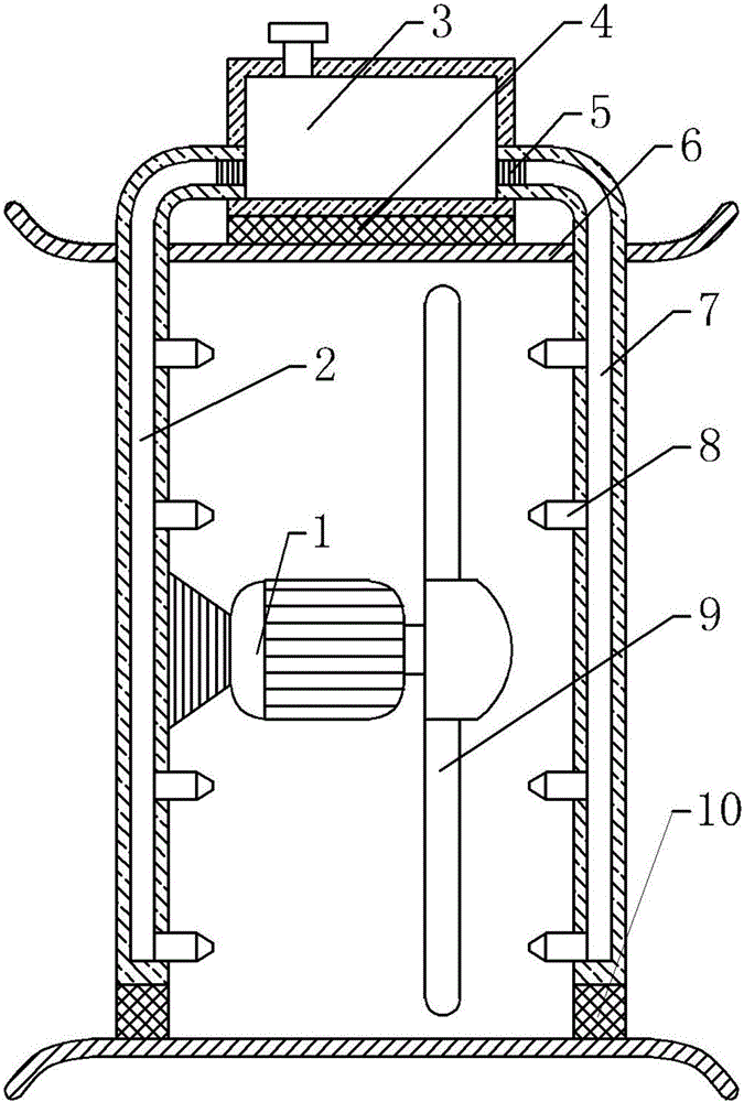
[0013] The present invention provides such figure 1 The shown fan with automatic cleaning function includes a reservoir 3, the end of the reservoir 3 is fixedly connected with a water inlet, and the front and rear ends of the reservoir 3 are fixedly connected with a rear conduit 2 and a front pipe 2 respectively. Conduit 7, described rear conduit 2 and front conduit 7 are all stainless steel tubes, described rear conduit 2 and front conduit 7 tops are all fixe...


PUM


Abstract

The invention discloses a draught fan with an automatic cleaning function. The draught fan comprises a water storage pond; a rear guiding pipe and a front guiding pipe fixedly communicate with the front end and the rear end of the water storage pond; the top end of the rear guiding pipe and the top end of the front guiding pipe are each fixedly provided with an electromagnetic valve; a driving motor is fixedly arranged on the middle portion of the rear guiding pipe; an output shaft of the driving motor is fixedly connected with a center shaft of fan blades; the water storage pond is fixedly connected with the upper end of a check ring through a first vibration reducing body; the bottom of the rear guiding pipe and the bottom of the front guiding pipe are both fixedly connected with the bottom end of the check ring through second vibration reducing bodies; and the side, close to the fan blades, of the rear guiding pipe and the side, close to the fan blades, of the front guiding pipe are each fixedly provided with a nozzle. The draught fan with the automatic cleaning function is reasonable in design, by means of a series of structures, the fan blades in the draught fan can be automatically cleaned, adverse effects, generated by dust on the fan blades, on the draught fan can be effectively prevented, and time and labor are saved.

Description

technical field [0001] The invention belongs to the technical field of fans, and in particular relates to a fan with automatic cleaning function. Background technique [0002] The fan is a machine that relies on the input mechanical energy to increase the gas pressure and discharge the gas. It is a driven fluid machine. When the fan starts to work, the vibration of the bearing part is very small, but as the running time increases, the dust in the fan will adhere to the impeller unevenly, gradually destroying the dynamic balance of the fan, and gradually increasing the vibration of the bearing. Once the vibration reaches the fan When the maximum allowable value is reached, the fan must be shut down for repair (remove dust accumulation, redo dynamic balance), because it is very dangerous at this time, and the user must not use it forcibly. The existing blower requires staff to remove the blower and manually clean the dust, which is time-consuming, laborious and inefficient. T...

Claims


Application Information

Patent Timeline
Patent Type & Authority Applications(China)
IPC IPC(8): F04D25/08F04D29/00F04D29/70
CPCF04D25/08F04D29/002F04D29/703
Inventor 王家银
Owner ZHANGJIAGANG ZHONGXIN FAN
Why Eureka
Try Eureka