Laser for laser equipment, with automatic cleaning function

A laser equipment and automatic cleaning technology, applied in laser parts, cleaning methods and utensils, cleaning methods using tools, etc., can solve the problems of lack of automatic cleaning and inconvenient application of laser equipment, and achieve the effect of improving the cleaning effect.

Inactive Publication Date: 2018-09-04
胡和萍
View PDF5 Cites 7 Cited by
  • Summary
  • Abstract
  • Description
  • Claims
  • Application Information

AI Technical Summary

Problems solved by technology

[0002] Laser is another major invention of mankind since the 20th century after nuclear energy, computers, and semiconductors. It is called "the fastest knife", "the most accurate ruler", and "the brightest light". , hence the name "laser", the light is emitted from the atoms that make up the matter, and the atoms are in an unstable state (that is, the excited state) after gaining energy, and it will emit energy in the form of photons, and the laser is the one that is captured The induced (excited) photon queue, the photons in this photon queue have the same optical characteristics and are extremely consistent. Laser applications are widely used, mainly including laser marking, laser welding, laser cutting, optical fiber communication, laser spectroscopy, and laser measurement. distance, laser radar, laser weapons, laser discs, laser pointers, laser vision correction, laser beauty, laser scanning, laser mosquito killers, etc.; The lasers equipped with most of the laser equipment do not have the function of automatic cleaning. After use, they often need to be cleaned manually, which brings inconvenience to the application of laser equipment.

Method used


Image

  • Laser for laser equipment, with automatic cleaning function
  • Laser for laser equipment, with automatic cleaning function

Examples


Embodiment Construction

[0019] The following will clearly and completely describe the technical solutions in the embodiments of the present invention with reference to the accompanying drawings in the embodiments of the present invention. Obviously, the described embodiments are only some, not all, embodiments of the present invention. Based on the embodiments of the present invention, all other embodiments obtained by persons of ordinary skill in the art without making creative efforts belong to the protection scope of the present invention.

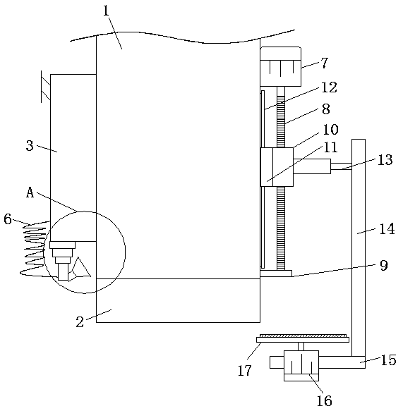
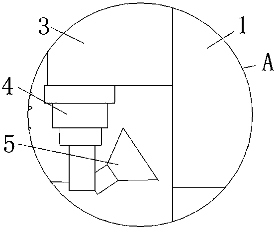
[0020] see Figure 1-2 , a laser device with automatic cleaning function, comprising a laser generator body 1, the bottom of the laser generator body 1 is fixedly connected to the top of the lens 2, one side of the laser generator body 1 is connected to one side of the cleaning liquid tank 3 One side of the cleaning liquid tank 3 is fixedly connected with a micropump, one side of the cleaning liquid tank 3 is fixedly connected with a feeding port, the bottom o...


PUM


Abstract

The invention relates to the technical field of laser equipment, and discloses a laser for laser equipment, with an automatic cleaning function. The laser for laser equipment, with an automatic cleaning function includes a laser generator body, wherein the bottom of the laser generator body is fixedly connected to the top of a lens; one side of the laser generator body is fixedly connected to oneside of a cleaning liquid tank; the bottom of the cleaning liquid tank is fixedly connected to the top of a first electric push rod; one side of the first electric push rod is fixedly connected to oneside of a spray head; and the spray head is fixedly connected to one side of a water tank through a connecting pipe fixedly connected to the back side thereof. Through a first motor fixedly connectedto one side of the laser generator body and a threaded sleeve threadedly connected to the surface of a threaded rod, by coordinating with the second electric push rod fixedly connected to one side ofthe threaded sleeve and a wiping plate fixedly connected to an output shaft of a second motor, the laser for laser equipment, with an automatic cleaning function, moves the wiping plate to the lens to wipe the lens for achieving the automatic cleaning effect.

Description

technical field [0001] The invention relates to the technical field of laser equipment, in particular to a laser for laser equipment with an automatic cleaning function. Background technique [0002] Laser is another major invention of mankind after nuclear energy, computers, and semiconductors since the 20th century. It is called "the fastest knife", "the most accurate ruler", and "the brightest light". , hence the name "laser", light is emitted from the atoms that make up the matter, and the atoms are in an unstable state (that is, excited state) after gaining energy, and it will emit energy in the form of photons, and the laser is the one that is captured The induced (excited) photon queue, the photons in this photon queue have the same optical characteristics, and the pace is extremely consistent. Laser applications are widely used, mainly including laser marking, laser welding, laser cutting, optical fiber communication, laser spectroscopy, and laser measurement. dista...

Claims


Application Information

Patent Timeline
Patent Type & Authority Applications(China)
IPC IPC(8): H01S3/02H01S5/02B08B1/00B08B1/04B08B3/02B08B11/00
CPCH01S3/02B08B1/006B08B1/04B08B3/02B08B11/00H01S5/02
Inventor 胡和萍
Owner 胡和萍
Why Eureka
Try Eureka