Substrate detection equipment

A technology for substrate detection and equipment, applied in measuring devices, optical testing of flaws/defects, and material analysis through optical means, can solve problems such as high equipment manufacturing costs and low efficiency, and achieve the effect of improving detection accuracy

Inactive Publication Date: 2016-09-14
深圳市振华兴科技有限公司
View PDF8 Cites 22 Cited by
  • Summary
  • Abstract
  • Description
  • Claims
  • Application Information

AI Technical Summary

Problems solved by technology

[0003] Due to the above inspection steps, the existing substrate inspection equipment needs to stop the board on the production line, and...

Method used


Image

  • Substrate detection equipment
  • Substrate detection equipment
  • Substrate detection equipment

Examples


Embodiment Construction

[0020] The present invention will be described in detail below in conjunction with the accompanying drawings and embodiments.

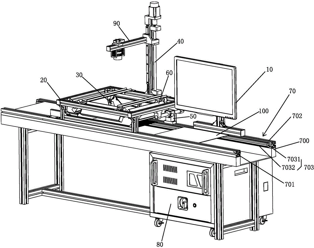
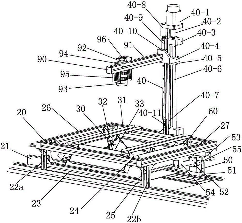
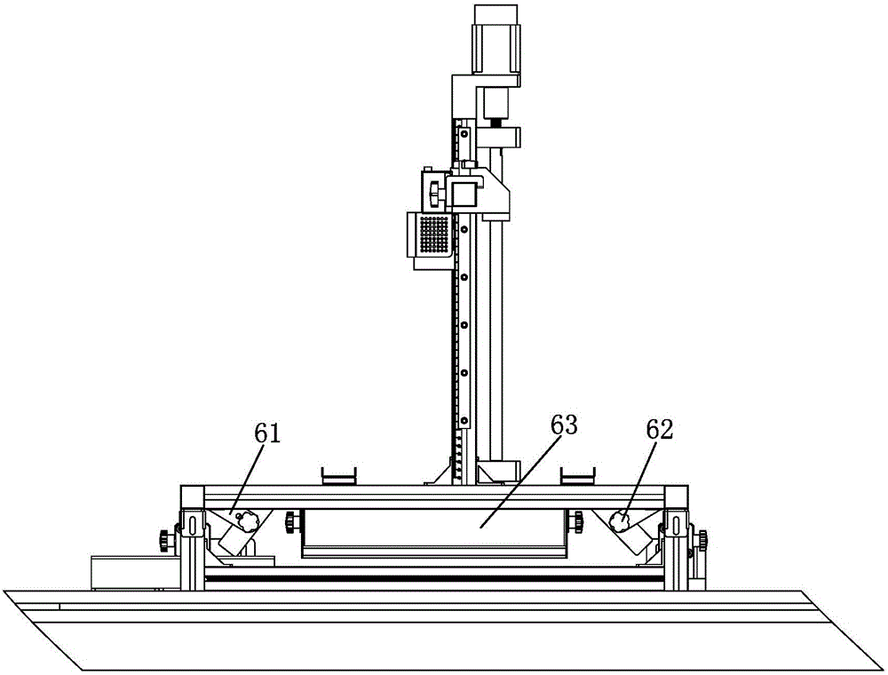
[0021] Please combine Figure 1 to Figure 4 For reference, the present invention provides a substrate inspection device, which is suitable for defect inspection of a substrate 100 such as a PCB circuit board or other plate-like workpieces. The substrate inspection equipment includes:

[0022] The transport mechanism 70 is used for transporting the substrate 100 . The transport mechanism 70 may be a SMT (Surface Mount Technology, Surface Mount Technology) production line or a docking station, which transports the substrate 100 from a previous process to a subsequent process.

[0023] The imaging mechanism 90 is arranged opposite to the conveying mechanism 70 , and is used to photograph the substrate 100 transported on the conveying mechanism 70 at a specific position to generate a complete image. The complete image can be understood as a panoramic i...


PUM


Abstract

The invention discloses substrate detection equipment. The substrate detection equipment comprises a transmission mechanism for delivering substrates; an imaging mechanism, which is opposite to the transmission mechanism and is used to take photos of substrates transmitted by the transmission mechanism at a time in a special position so as to generate complete images; and a control mechanism, which is electrically connected to the imaging mechanism and is used to control the photo shooting of the imaging mechanism, store and analyze the complete images, and detect the defects of the substrates; wherein the imaging mechanism comprises a high pixel camera and a high resolution industrial lens installed on the high pixel camera, and the high pixel camera is electrically connected to the control mechanism and is controlled by the control mechanism. The provided substrate detection equipment can automatically detects the defects during the substrate transportation process without stopping the transmission mechanism, moreover, the substrates do not need to be fixed, and the one time imaging detection precision is high.

Description

technical field [0001] The invention relates to the technical field of substrate detection, in particular to a substrate detection device. Background technique [0002] Most of the existing substrate inspection equipment uses the camera to cross each other on the X and Y axes to take multi-point and multiple camera imaging pictures, and then use the inspection software to stitch multiple images into a complete image to identify substrates such as circuit boards. or manufacturing defects in the workpiece. [0003] Due to the need for the above detection steps, the existing substrate inspection equipment needs to stop the board on the production line, and after the workpiece is inspected, it is transported to the next process, which is inefficient and the equipment manufacturing cost is too high. Contents of the invention [0004] In order to solve the above technical problems, the present invention provides a substrate detection device, which can automatically complete def...

Claims


Application Information

Patent Timeline
IPC IPC(8): G01N21/84G01N21/88G01N21/89G01N21/956
CPCG01N21/84G01N21/8806G01N21/8901G01N21/956G01N2021/8411G01N2021/845G01N2021/8835G01N2021/8908G01N2021/95638
Inventor 廖怀宝
Owner 深圳市振华兴科技有限公司
Why Eureka
Try Eureka