Combined type locker

A locker and combined technology, which is applied in the field of machinery, can solve the problems of inconvenient use, limited storage space, and being eaten by insects, etc., and achieve the effect of diversified adjustment methods, wide adjustment range, and simple structure

Active Publication Date: 2016-09-21
湖南全艺家具制造有限公司
View PDF5 Cites 3 Cited by
  • Summary
  • Abstract
  • Description
  • Claims
  • Application Information

AI Technical Summary

Problems solved by technology

Among them, the space size of the office environment limits the volume of the lockers, so that the storage space is limited, and the general locker layout is mostly fixed, and the user cannot flexibly adjust the storage space, resulting in the large samples cannot be placed , or can only change the placement method, such as inclined placement, but this placement is easy to damage the sample, and there is still extra space after the smaller sample is placed, resulting in a waste of space, so the existing lockers are inconvenient to use , the storage space cannot be fully utilized
[0003] Secondly, the existing lockers only serve the function of storage and do not involve the maintenance of items. Lockers are generally made of wood and are prone to moisture or insects. Once damp, the items placed inside are also vulnerable to damage. influences
Among them, a lot of bolts and screws are used to connect the parts of the locker. These bolts and screws are exposed, which will not only affect the overall appearance of the cabinet, but also easily rust after the cabinet is damp.
[0004] In addition, other office appliances are used in daily office work, which cannot be placed reasonably when the office space is limited
Therefore, based on the above problems, the existing lockers can no longer meet the requirements of modern office workers, and it is urgent to make certain improvements with the times.

Method used


Image

  • Combined type locker
  • Combined type locker
  • Combined type locker

Examples


Embodiment Construction

[0030] The following are specific embodiments of the present invention and in conjunction with the accompanying drawings, the technical solutions of the present invention are further described, but the present invention is not limited to these embodiments.

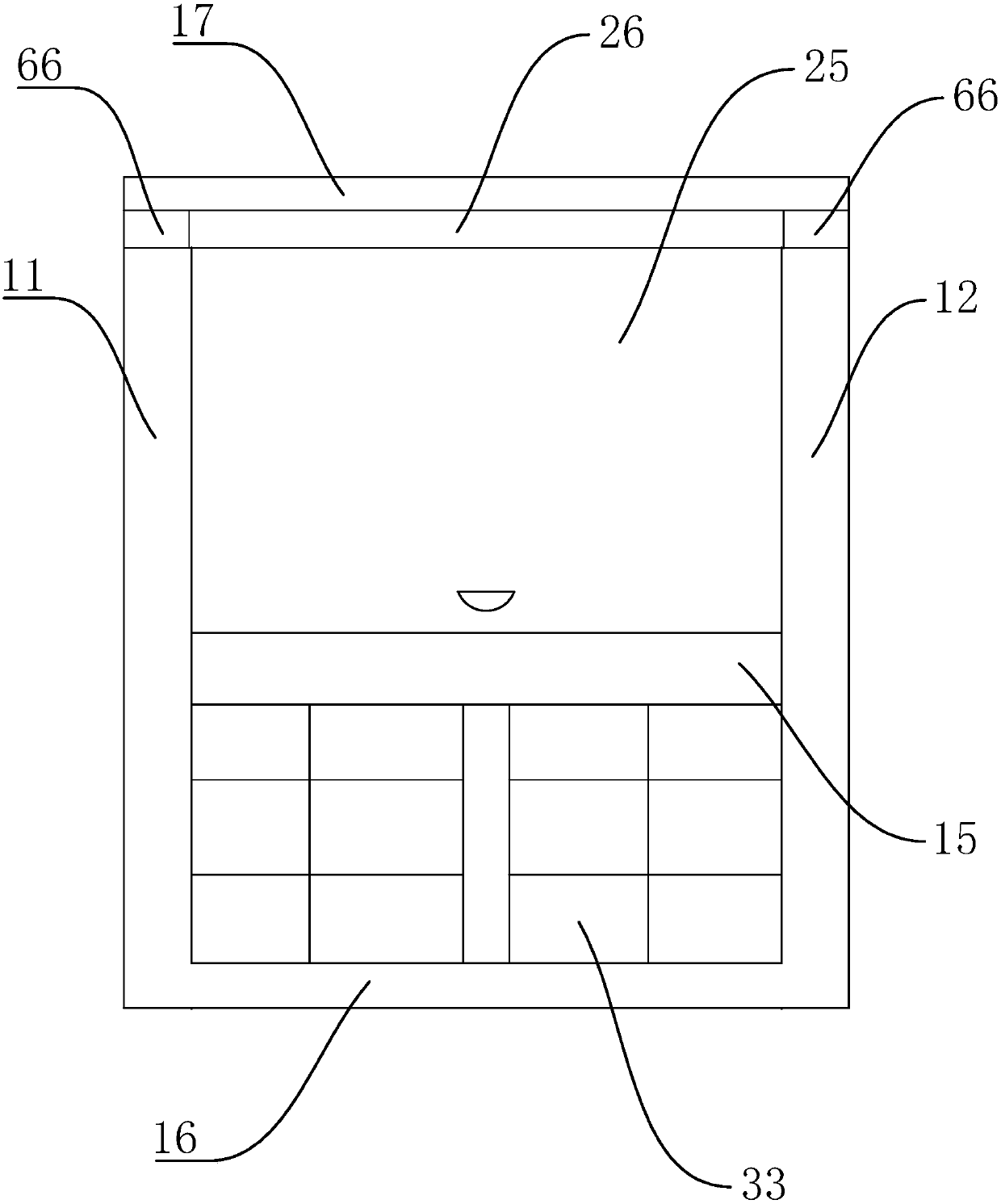
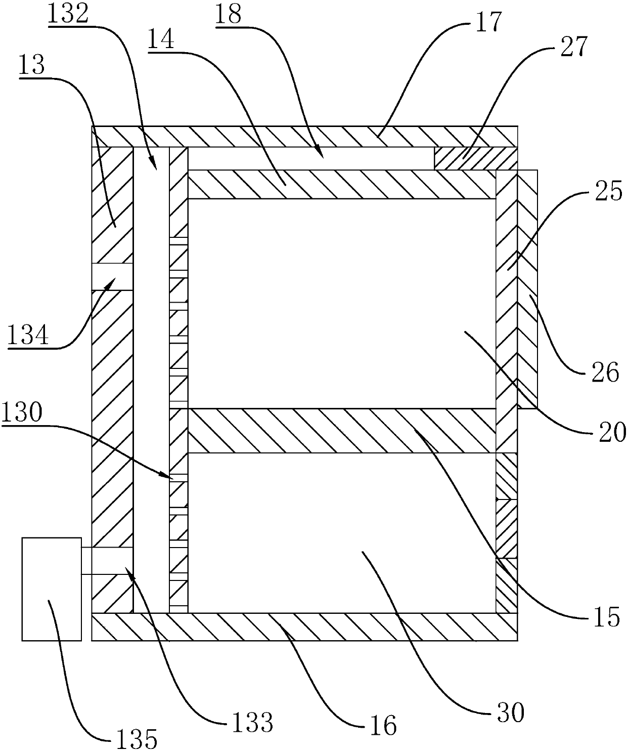
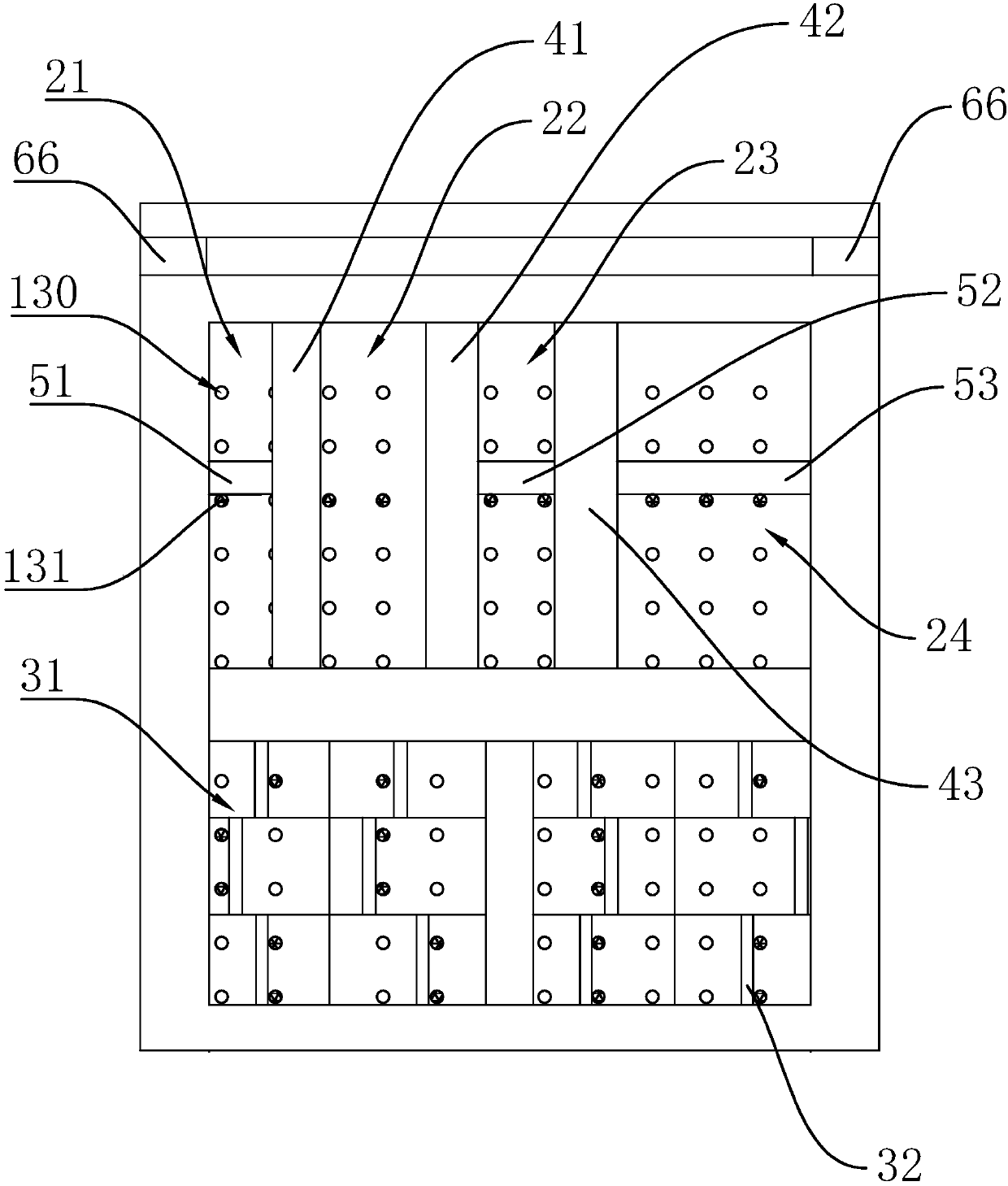
[0031] Such as Figure 1 to Figure 7 As shown, the present invention provides a combined locker, comprising a cabinet body composed of cabinet panels, the cabinet panels include a left cabinet panel 11, a right cabinet panel 12, a rear cabinet panel 13, an upper cabinet panel 14, and a middle panel 15 And the lower cabinet 16; The back cabinet 13, the middle board 15 and the lower cabinet 16 surround the lower cabinet 30 for placing documents; A chute 66 is provided, and the top plate 17 and the upper cabinet board 14 form a whiteboard cavity 18 for accommodating the whiteboard 26, which is rotatably connected to the upper cabinet body 20; the locker also includes an upper cabinet door for opening and closing the upper ca...


PUM


Abstract

The invention provides a combined type locker. The combined type locker comprises a locker body composed of locker boards, wherein the locker boards include the left locker board, the right locker board, the rear locker board, the upper locker board, the middle board and the lower locker board, an upper locker body used for accommodating items is defined by the left locker board, the right locker board, the rear locker board, the upper locker board and the middle board, and a lower locker body used for accommodating documents is defined by the left locker board, the right locker board, the rear locker board, the middle board and the lower locker board; the locker boards further include the top board located on the top of the upper locker board, sliding chutes are formed between the two ends of the top board and the upper locker board, a white board cavity used for accommodating a white board is formed by the top board and the upper locker board, and the white board is connected to the upper locker body in a rotary mode. The locker further comprises an upper locker door used for opening and closing the upper locker body and a lower locker door used for opening and closing the lower locker body. The locker has a white board writing function and is suitable for an office site with limited space.

Description

technical field [0001] The invention belongs to the technical field of machinery and relates to office furniture, in particular to a combined locker. Background technique [0002] With the improvement of people's living standards, people's requirements for the living and office environment around them are becoming higher and higher. In daily office work, lockers are an indispensable office furniture. In order to improve confidentiality, it is important All documents and customer samples must be placed in the locker. Among them, the space size of the office environment limits the volume of the lockers, so that the storage space is limited, and the general locker layout is mostly fixed, and the user cannot flexibly adjust the storage space, resulting in the large samples cannot be placed , or can only change the placement method, such as inclined placement, but this placement is easy to damage the sample, and after the smaller sample is placed, there is still extra space, res...

Claims


Application Information

Patent Timeline
Patent Type & Authority Applications(China)
IPC IPC(8): A47B47/00A47B83/00
CPCA47B47/00A47B83/00
Inventor 林晓丽陈晔
Owner 湖南全艺家具制造有限公司
Why Eureka
Try Eureka