Stirring tank washing device

A technology for cleaning devices and mixing barrels, which is applied in the field of cleaning devices for cleaning mixing barrels of mixers, which can solve the problems of manpower consumption and long cleaning time of mixing barrels, and achieve the effects of saving costs, saving cleaning time, and improving production efficiency

Inactive Publication Date: 2016-09-21
KUNSHAN AT & MIK METAL MATERIALS CO LTD
View PDF2 Cites 3 Cited by
  • Summary
  • Abstract
  • Description
  • Claims
  • Application Information

AI Technical Summary

Problems solved by technology

[0004] The purpose of the present invention is to propose a mixing tank cleaning device, which

Method used


Image

  • Stirring tank washing device
  • Stirring tank washing device

Examples


Embodiment Construction

[0021] In order to enable those skilled in the art to better understand the technical solution of the present invention, the technical solution of the present invention will be further described below in conjunction with the accompanying drawings and through specific implementation methods.

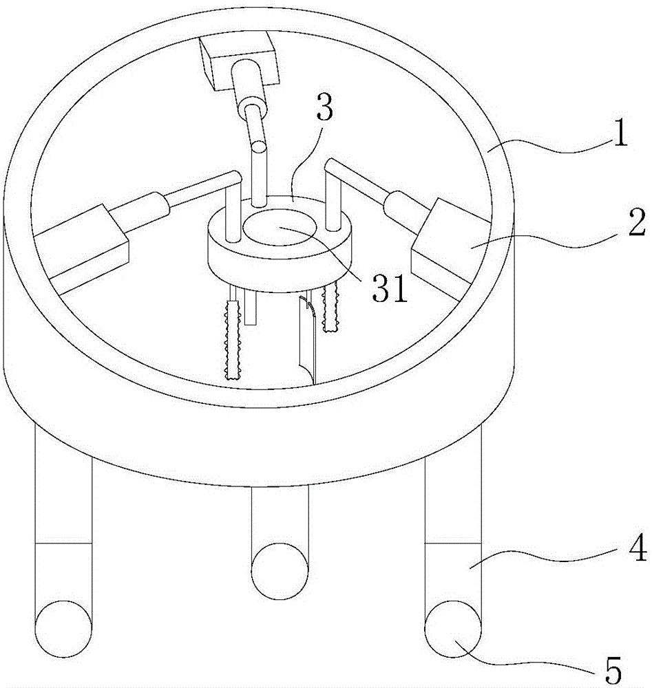
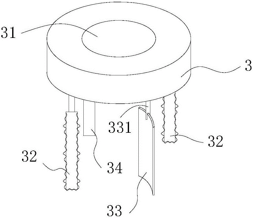
[0022] This embodiment discloses a mixing tank cleaning device, such as figure 1 As shown, the cleaning device includes a cleaning mechanism and a frame 1, the frame 1 is an annular structure, and the cleaning mechanism is arranged inside the frame 1, and the cleaning mechanism includes a cleaning tray 3, the top of the cleaning tray 3 is suspended on the inside of the frame 1 by no less than two telescopic mechanisms 2, and the number of telescopic mechanisms 2 in this embodiment is three, wherein the telescopic mechanism 22 is connected to the outer side of the cleaning tray 3 The wall is connected or the telescopic mechanism 22 is connected to the top of the cleaning tray 3 through a c...


PUM


Abstract

The invention relates to the technical field of stirring machines, in particular to a washing device for washing the stirring tank of a stirring machine. The stirring tank washing device comprises a washing mechanism and a rack, wherein the rack is of an annular structure; the washing mechanism is arranged on the inner side of the rack; the washing mechanism comprises a washing disc; the upper part of the washing disc is suspended on the inner side of the rack through at least two telescopic mechanisms; the telescopic mechanisms are uniformly distributed on the inner side wall of the rack in the circumferential direction; through holes through which stirring shafts pass are formed in the washing disc in the axial direction of the washing disc. As at least two telescopic mechanisms are arranged on the washing disc, and the washing disc is enabled to rotate counterclockwise or clockwise when the telescopic mechanisms stretch or withdraw, the washing disc can contact the inner side wall of the stirring tank, a function of rotating and washing the stirring tank can be achieved, and meanwhile as the through holes through which the stirring shafts pass are formed in the washing disc in the axial direction of the washing disc, stirring blades do not need to be disassembled from the stirring tank before washing, and the washing time is further shortened.

Description

technical field [0001] The invention relates to the technical field of mixers, in particular to a cleaning device for cleaning the mixing tank of the mixer. Background technique [0002] Household blenders are easy to clean during the cleaning cycle due to their small size and the low number of daily applications. However, industrial mixers are different from household mixers. Industrial mixers are used a lot every day and are in working condition for a long time. Due to the large volume of industrial mixers, it takes a lot of time to clean them. At the same time, most of the industrial mixers in the factory are cleaned manually, which directly leads to prolonged cleaning time and labor-intensive cleaning, which directly leads to high production costs and low production efficiency. [0003] Therefore, how to propose a device for cleaning the mixing tank to solve the long time and labor-consuming cleaning of the existing mixing tank is a technical problem to be solved by tho...

Claims


Application Information

Patent Timeline
IPC IPC(8): B01F15/00
CPCB01F35/123B01F2101/1805
Inventor 何建久孟坤全祁新亮崔晓波
Owner KUNSHAN AT & MIK METAL MATERIALS CO LTD
Why Eureka
Try Eureka