Wafer slicer, roller module thereof, and method for slicing wafer

A slicing machine and wafer technology, applied to metal sawing equipment, fine working devices, working accessories, etc., can solve the problems of affecting the wafer slicing accuracy, uneven distribution, and reducing the service life of the roller 11, so as to reduce cutting The effects of wire shaking, shortened process time, and high slicing accuracy

Inactive Publication Date: 2017-08-29
AUO CRYSTAL
View PDF5 Cites 16 Cited by
  • Summary
  • Abstract
  • Description
  • Claims
  • Application Information

AI Technical Summary

Problems solved by technology

[0006] In addition, reducing the diameter of the roller 11 may also cause two problems: 1. The outer diameter of the roller 11 is reduced, so that the curvature of the axis around which the cutting line segment 121 is wound becomes larger. The cutting line segment 121 may generate a large stress on the roller 11, and it is easy to cut down the surface layer of the roller 11, and cause the position of part of the cutting line segment 121 to move down and unevenly distribute, thereby affecting the accuracy of wafer slicing, and detracting from the The service life of described roller 11
[0007] In addition, using the wafer slicer 1 to cut the ingot 10 is easy to obtain a wafer with a dirty surface, so that the subsequent cleaning process of the wafer needs more cleaning time, which is not conducive to the improvement of the overall production capacity.

Method used


Image

  • Wafer slicer, roller module thereof, and method for slicing wafer
  • Wafer slicer, roller module thereof, and method for slicing wafer
  • Wafer slicer, roller module thereof, and method for slicing wafer

Examples


Embodiment Construction

[0071] The present invention will be described in detail below in conjunction with the accompanying drawings and embodiments.

[0072] Before the present invention is described in detail, it should be noted that in the following description, similar elements are denoted by the same numerals.

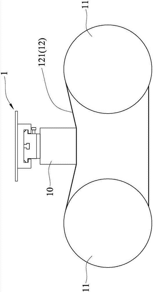
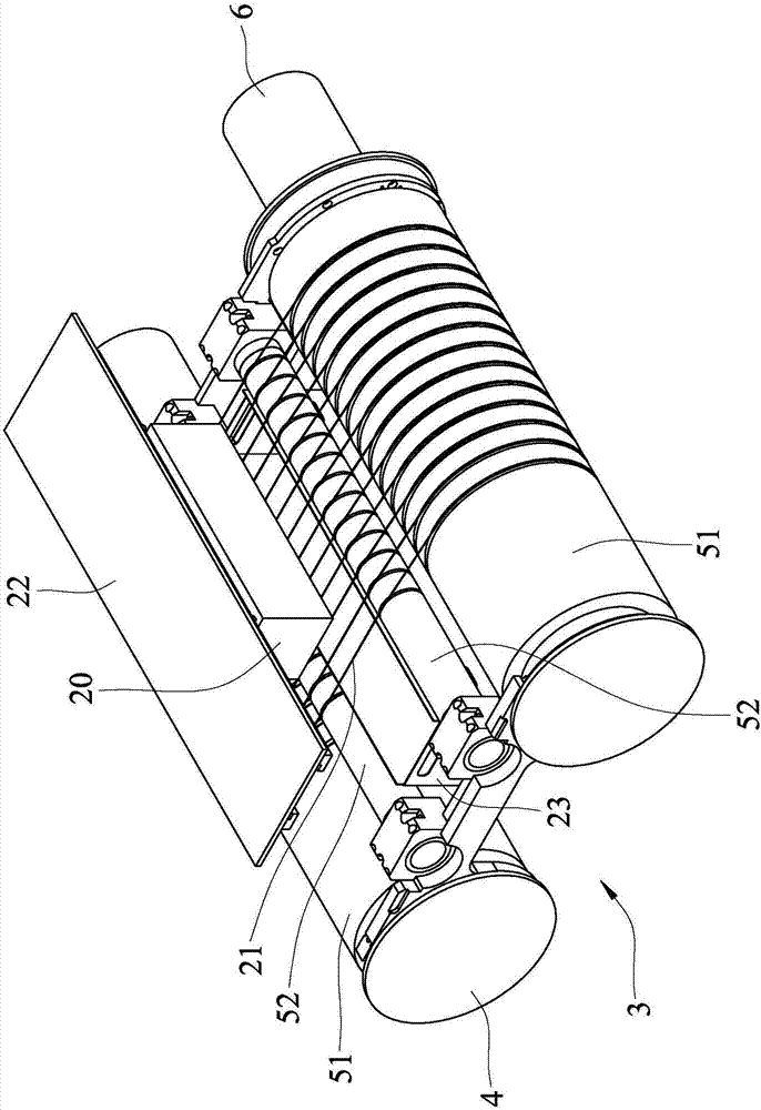
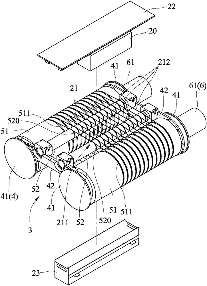
[0073] refer to figure 2 and image 3 , the first embodiment of the wafer slicer of the present invention includes a feeding unit 22 for installing a crystal rod 20 and driving the crystal rod 20 to move down, a cutting line 21 for installing and driving the cutting unit The wire 21 cuts the wheel structure 3 of the ingot 20 , and a fragment groove 23 located under the feeding unit 22 and the ingot 20 . The fragment groove 23 is used to accept the fragments of the ingot 20 that accidentally falls during the cutting operation.

[0074] The wheel set structure 3 includes a supporting unit 4 , two main rollers 51 , two auxiliary rollers 52 , and a driving unit 6 . In this embodiment, t...


PUM

PropertyMeasurementUnit
diameteraaaaaaaaaa
diameteraaaaaaaaaa
diameteraaaaaaaaaa

Abstract

A wafer slicer and a roller module thereof are provided. The wafer slicer comprises a feeding unit and the roller module. The roller module is used for driving a sawing wire to slice an ingot, and includes two spaced apart main rollers and an auxiliary roller. A horizontal plane is defined to pass through the rotating axes of the main rollers. Two vertical planes are defined to be perpendicular to the horizontal plane and respectively pass through the rotating axes. The auxiliary roller has a diameter smaller than one half of the diameter of each of the main rollers. The auxiliary roller is disposed above the horizontal plane and between the vertical planes. An uppermost side of the auxiliary roller is not lower than an uppermost side of each main roller. The main rollers and the auxiliary roller are adapted for the sawing wire to be wound thereon to form a wire net that spans over the main rollers and the auxiliary roller for slicing the ingot. Moderate support can be provided for the sawing wire to reduct vibration of the sawing wire, to achieve high slicing precision, and to avoid interference on saw ingot. The invention also provides a method for slicing the wafer.

Description

technical field [0001] The present invention relates to a wheel set structure, wafer slicing equipment and a slicing method, in particular to a wheel set structure suitable for a wafer slicer, a wafer slicer using the wheel set structure, and a wafer slicer Methods. Background technique [0002] refer to figure 1 , an existing wafer slicer 1 includes a pair of rollers 11 and a cutting wire 12 wound thereon. The cutting wire 12 is wound on the roller 11 and divided into a plurality of cutting wire segments 121 , and the cutting wire segments 121 are moved left and right by the forward and reverse rotation of the roller 11 to form several wire saws. When in use, one crystal rod 10 moves down and presses into the cutting line segment 121, and is cut into multiple wafers. [0003] With the evolution of the industry, the process of wafer slicing continues to improve, and the cutting wire 12 is gradually thinned, which can help reduce costs. However, under the same force, the w...

Claims


Application Information

Patent Timeline
Patent Type & Authority Applications(China)
IPC IPC(8): B28D5/04B28D7/00
CPCB28D5/042B28D7/00B23D57/0053B23D57/0061B28D5/045B28D5/0076
Inventor 雷世爵郭智扬詹志鸿陈展添邱少晖
Owner AUO CRYSTAL
Why Eureka
Try Eureka