Liner-driven type software robot with changeable rigidity

A wire-driven and robotic technology, applied in manipulators, program-controlled manipulators, manufacturing tools, etc., can solve the problems of stiffness adjustment and motion coupling that cannot be independently controlled, poor stiffness and compliance, etc., and achieve good and flexible compliance control, Wide range of applications, guaranteed integrity of the effect

Active Publication Date: 2016-09-21
HARBIN INST OF TECH
View PDF7 Cites 39 Cited by
  • Summary
  • Abstract
  • Description
  • Claims
  • Application Information

AI Technical Summary

Problems solved by technology

[0006] The purpose of the present invention is to provide a wire-driven variable stiffness soft robot to solve the problem that the current soft robot sacrifices stiffness to improve compliance, resulting in poor stiffness and compliance. The existing stiffness variable soft robot has stiffness adjustment and kinematic coupling are not independently controllable

Method used


Image

  • Liner-driven type software robot with changeable rigidity
  • Liner-driven type software robot with changeable rigidity
  • Liner-driven type software robot with changeable rigidity

Examples


specific Embodiment approach 1

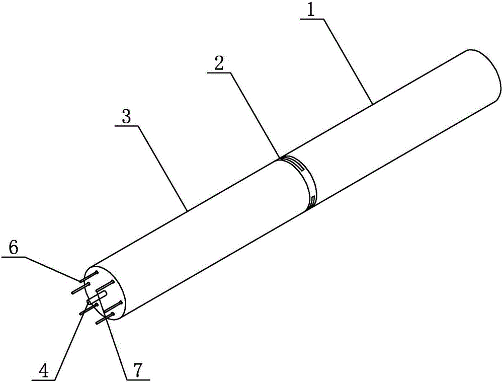
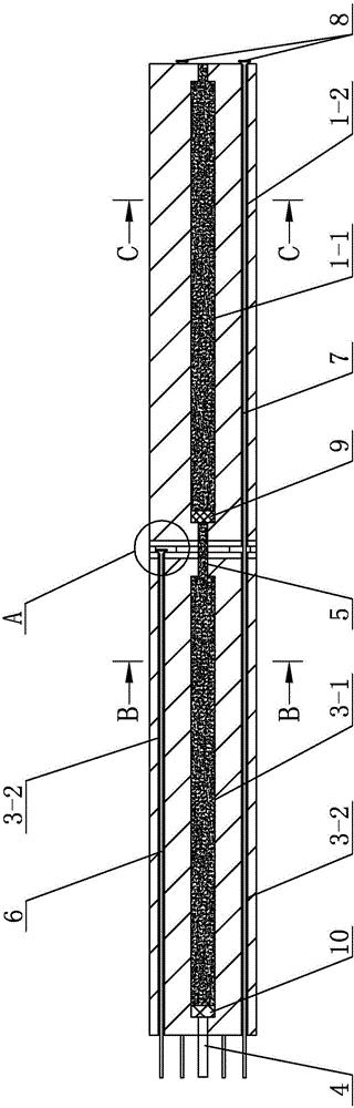
[0024] Specific implementation mode one: combine figure 1 , figure 2 , image 3 , Figure 4 , Figure 5 , Figure 6 , Figure 7 , Figure 8 and Figure 9 Describe this embodiment, this embodiment comprises front driving arm 1, connection module 2, rear driving arm 3, end blocking connecting pipe 4, middle blocking connecting pipe 5, at least three first driving wires 6 and at least three second driving Wire rope 7, the front driving arm 1 and the rear driving arm 3 are soft driving arms, the inside of the rear driving arm 3 is processed with a rear blocking chamber 3-1 and at least six rear rope driving chambers along its length direction 3-2, at least six rear string driving chambers 3-2 are evenly arranged around the rear blocking chamber 3-1, and the inside of the front driving arm 1 is respectively processed with the front blocking chamber 1-1 and at least Three front string drive chambers 1-2, at least three front string drive chambers 1-2 are evenly arranged aro...

specific Embodiment approach 2

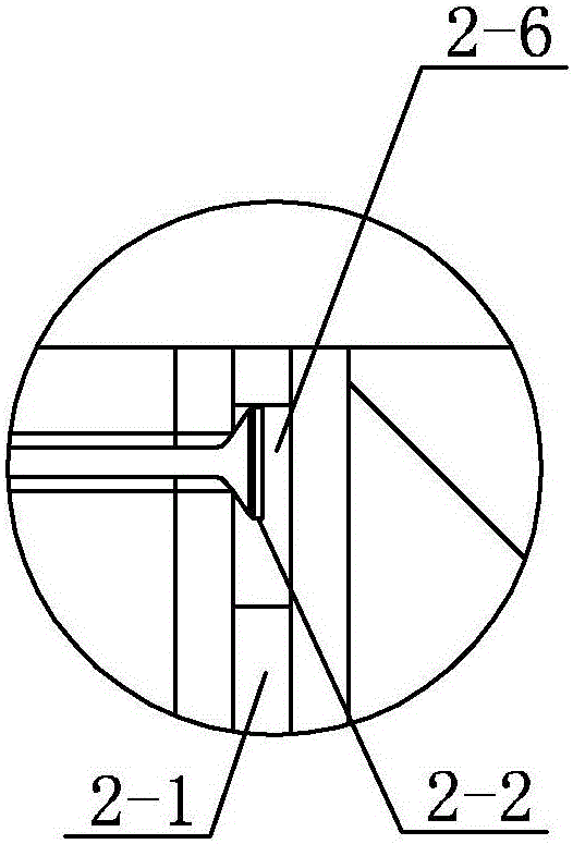
[0033] Specific implementation mode two: combination Figure 1 to Figure 9 Describe this embodiment, in this embodiment, the outer shape of the front driving arm 1 and the rear driving arm 3 are both cylindrical, and the connecting module 2 includes a disc-shaped body 2-1 and at least three first limit blocks 2 -2, the connection module 2 is respectively processed with a vent hole 2-3, at least three first wire rope through holes 2-4 and at least three second wire rope through holes 2-5 along its axial direction, the connection The module 2 is processed with at least three limiting block placement grooves 2-6 along its radial direction, and a first limiting block 2-2 is placed in each limiting block placement groove 2-6, and the first wire rope through hole 2-4 and the second wire rope through holes 2-5 are alternately arranged around the vent hole 2-3, and one end of each first wire rope through hole 2-4 corresponds to the rear wire driving chamber of the first driving wire r...

specific Embodiment approach 3

[0036] Specific implementation mode three: combination figure 2 Describe this embodiment, in this embodiment it also includes at least three second limit blocks 8, one end of each second driving wire 7 is connected with the winding reel, and the other end of each second driving wire 7 Pass through its corresponding rear string drive cavity 3-2, second string through hole 2-5 and front string drive cavity 1-2 in sequence and be fixedly connected on the front drive arm 1 through a second limit block 8.

[0037] The function of the second limit block 8 in this embodiment is to fix the position of the second driving wire 7 . Other unmentioned structures and connections are the same as those in the second embodiment.


PUM


Abstract

The invention provides a liner-driven type software robot with changeable rigidity, and relates to a software robot. A conventional software robot has the defects that the flexibility is improved by reducing rigidity, so that the robot is poor in rigidity and flexibility; the conventional software robot with changeable rigidity has the problem that rigidity regulating and motion coupling cannot be independently controlled. According to the liner-driven type software robot disclosed by the invention, a front blocking cavity and at least three front ropeyarn driving cavities are formed in a front driving arm, wherein the front ropeyarn driving cavities are uniformly distributed around the front blocking cavity; a connecting module is arranged between the front driving arm and a rear driving arm; each of the front ropeyarn driving cavities corresponds to a rear ropeyarn driving cavity through the connecting module, and communicates with the corresponding rear ropeyarn driving cavity; two ends of a middle blocking connecting pipe respectively communicate with the front blocking cavity and a rear blocking cavity; solid particles are stuffed in the front blocking cavity and the rear blocking cavity; an end part blocking connecting pipe communicates with the rear blocking cavity. The liner-driven type software robot disclosed by the invention is used for physical assisting medical rehabilitation, minimally invasive surgeries, and complex environmental scanning and detection operation.

Description

technical field [0001] The invention specifically relates to a wire-driven soft robot with variable stiffness. Background technique [0002] In recent years, with the development of new materials and rapid processing and manufacturing technology, soft robot technology has become a research hotspot in the field of robotics. Soft robot technology involves the disciplines of bionics, soft matter and robotics. Compared with traditional rigid robots, it has many advantages: it has infinite degrees of freedom in theory, does not require complex mechanisms, and is easy to achieve multifunctionality. ;It can better adapt to the unknown or complex unstructured working environment through deformation; it has flexible contact with the working object, can operate objects with complex and different shapes, and has little damage to itself and the operating object, etc. It has broad application prospects in rehabilitation, minimally invasive surgery, complex environment search and detecti...

Claims


Application Information

Patent Timeline
Patent Type & Authority Applications(China)
IPC IPC(8): B25J9/10
CPCB25J9/104
Inventor 闫继宏张新彬董红兵赵杰
Owner HARBIN INST OF TECH
Why Eureka
Try Eureka