

Multi-nozzle 3D spray-head, printing method, and 3D printer
A 3D printer and 3D printing technology, applied in the direction of additive processing, etc., can solve the problems of no practical value, wide material spacing, no material, etc., to achieve the effect of improving utilization, reducing energy loss, and simplifying control methods
- Summary
- Abstract
- Description
- Claims
- Application Information
AI Technical Summary
Problems solved by technology
Method used
Image

Examples
Embodiment 1
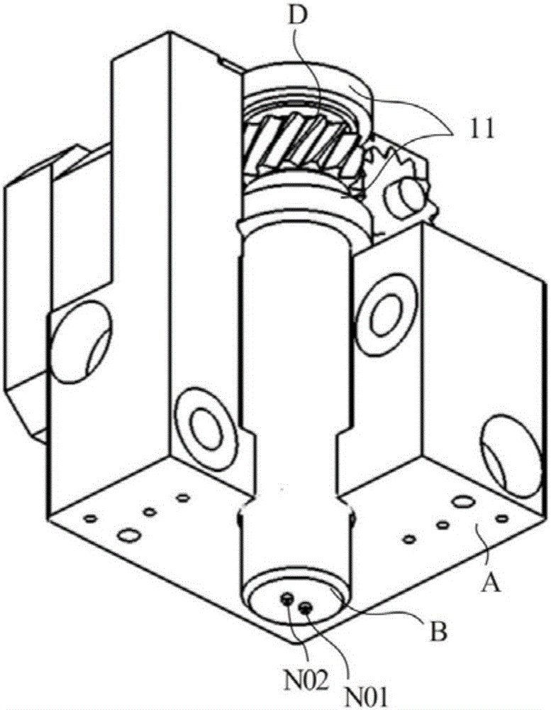
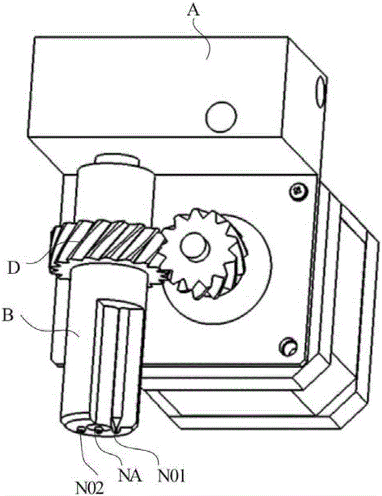
[0107] see figure 1 As shown, a cross-sectional view of a multi-nozzle 3D printing nozzle, this embodiment specifically provides a printing nozzle, including a nozzle seat A, a nozzle seat B, and a driving device D. Wherein, at least two nozzles are arranged on the printing nozzle, the nozzle seat B is movably arranged on the nozzle seat A, and at least one nozzle N is arranged on the nozzle seat B. See figure 1 As shown, two nozzles N01 and N02 are set on the nozzle seat B; see figure 2 As shown, two nozzles N01 and N02 are set on the nozzle seat B, and one nozzle NA is set on the nozzle seat A. When in use, the driving device D drives the nozzle seat B to move, and the printing nozzle drives the two nozzles N01 and N02 to move along the set printing path and complete printing.
[0108] It should be noted that in figure 1 The middle nozzle seat B is slidingly sleeved on the inner side of the nozzle seat A, and preferably the midpoint of the line connecting the two noz...
Embodiment 2
[0112] The structure and working principle of the second embodiment and the first embodiment are basically the same, see Figure 5 As shown, the only difference is that the nozzle seat includes the first nozzle seat B1, the second nozzle seat B2 and the third nozzle seat B3, and at least one first nozzle N1 is set on the first nozzle seat B1, and the second nozzle seat At least one second nozzle N2 is arranged on B2, and at least one third nozzle N3 is arranged on the third nozzle seat B3. Meanwhile, the driving device D includes a first driving device D1 , a second driving device D2 , and a third driving device D3 . Wherein, the first nozzle seat B1 is connected to the first driving device D1 and is driven to move by the first driving device D1; the second nozzle seat B2 is connected to the second driving device D2 and is driven to move by the second driving device D2; The third nozzle seat B3 is connected with the third driving device D3, and is driven to move by the third ...
Embodiment 3
[0121] The structure and working principle of the third embodiment are basically the same as those of the second embodiment, and the first nozzle seat B1, the second nozzle seat B2 and the third nozzle seat B3 are arranged concentrically along the same central axis. see Figure 8 As shown, the only difference is that the third driving device D3 is arranged on the nozzle seat A, the second driving device D2 is fixed on the third nozzle seat B3, and the first driving device D1 is fixed on the second nozzle seat B2. In this way, the third nozzle seat B3 can be driven to rotate relative to the nozzle seat A through the third driving device D3, and at the same time, the second driving device D2 connected to the third nozzle seat B3 can drive the second nozzle seat B2 to rotate, and the second nozzle seat B2 can be rotated with the second nozzle The first drive device D1 connected to the seat B2 drives the first nozzle seat B1 to rotate, thereby realizing the one-way linkage functio...
PUM
 Abstract
Description
Claims
Application Information