3D printing pen and its printing method
A 3D printing pen and printing pen technology, applied in the field of 3D printing, can solve problems such as difficulty in forming three-dimensional objects, inability to effectively extrude filaments, clogged nozzles, etc., achieve good heat dissipation effects, facilitate disassembly and assembly, and improve printing accuracy.
- Summary
- Abstract
- Description
- Claims
- Application Information
AI Technical Summary
Problems solved by technology
Method used
Image

Examples
no. 1 example
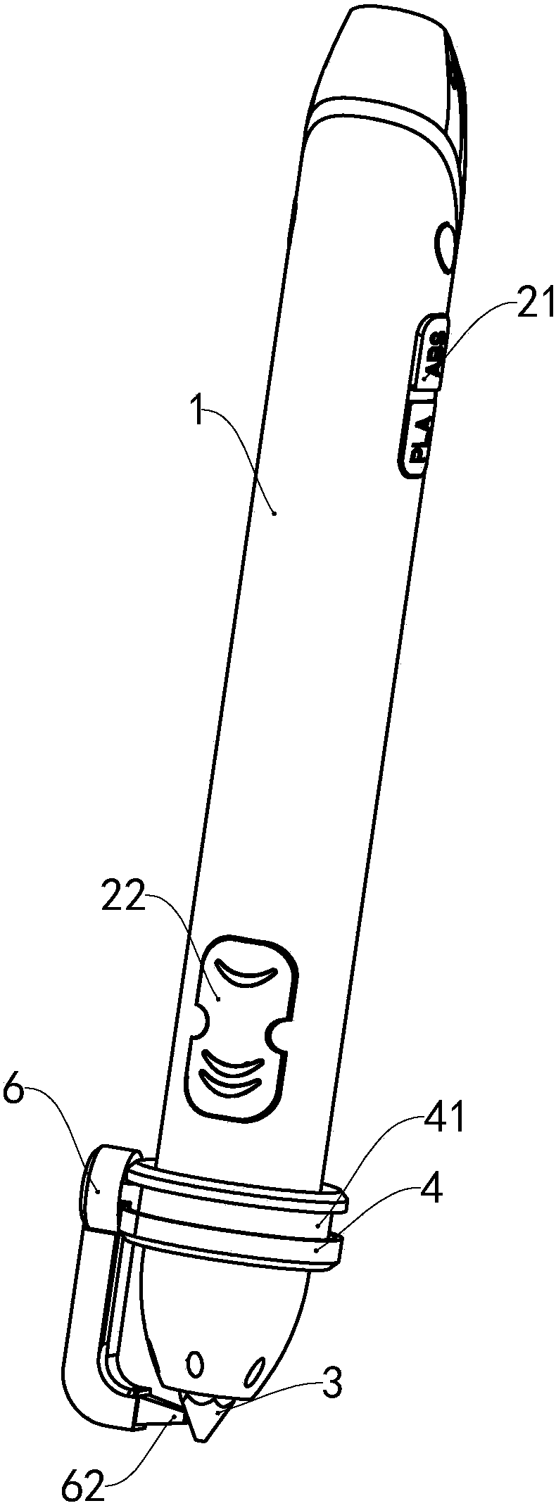
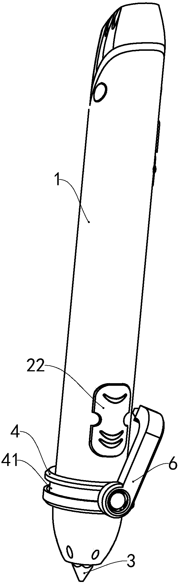
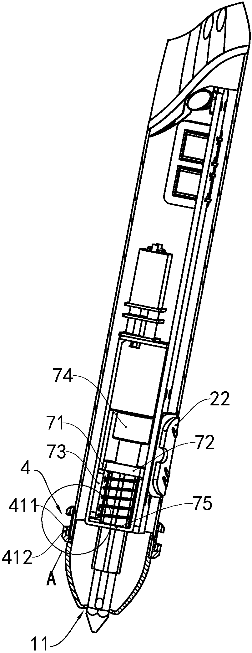
[0037] see Figure 1 to Figure 3 , the 3D printing pen of this embodiment includes a casing 1, control buttons 21, 22 and a nozzle 3, the first end of the casing 1 is provided with an opening 11, the control buttons 21, 22 are installed on the casing 1, and the nozzle 3 is arranged on the casing 1. The first end and protrudes from the opening 11 . The 3D printing pen further includes a fixed part 4 , a moving part 5 and a cooling device 6 , wherein the fixed part 4 is arranged on the casing 1 at a position close to the opening 11 , the fixed part 4 is provided with a conductive part, the moving part 5 and the fixed part 4 It is slidably fitted in the circumferential direction of the housing 1, and at least a part of the moving part 5 is made of conductive material. In addition, the cooling device 6 is movably connected to the moving part 5. The cooling device 6 is provided with a cooling fan and a motor. The end is provided with an air outlet 62 , and the air outlet 62 corres...
no. 2 example
[0046] As a description of the second embodiment of the print head of the present invention, only the differences from the first embodiment of the 3D printing pen described above will be described below.
[0047] see Figure 7 , the shape of the fixed part 14 and the moving part 15 can also be set to the following structure. The guide groove 141 of the fixing member 14 includes a structure of an upper groove 1411 and a lower groove 1412. The upper groove 1411 and the lower groove 1412 are opened around the circumferential direction of the fixing member 14 and are respectively arranged at two ends of the fixing member 14. The engaging part 151 of the moving part 15 has an upper protrusion 1511 and a lower protrusion 1512, the upper protrusion 1511 is installed in the upper groove 1411 and can slide in the upper groove 1411, and the lower protrusion 1512 is installed in the lower groove 1412 and can slide in the lower groove 1412 , that is, the moving part 15 can rotate around ...
PUM
 Abstract
Description
Claims
Application Information
 - R&D Engineer
- R&D Manager
- IP Professional
- Industry Leading Data Capabilities
- Powerful AI technology
- Patent DNA Extraction
Browse by: Latest US Patents, China's latest patents, Technical Efficacy Thesaurus, Application Domain, Technology Topic.
© 2024 PatSnap. All rights reserved.Legal|Privacy policy|Modern Slavery Act Transparency Statement|Sitemap