Novel large-stroke compliant parallel micro positioning platform

A technology of micro-positioning platform and large stroke, which is applied in the direction of machine/bracket, lifting device, lifting frame, etc., which can solve the problems of small deformation and limited working space, and achieve the effect of simple structure

Active Publication Date: 2016-09-21
FOSHAN UNIVERSITY
View PDF6 Cites 7 Cited by
  • Summary
  • Abstract
  • Description
  • Claims
  • Application Information

AI Technical Summary

Problems solved by technology

[0005] The purpose of the present invention is to overcome the shortcomings and deficiencies in the prior art, and provide a new type of large-stroke compliant parallel micro-positioning platform that has a simple structure and can realize the rotation and

Method used


Image

  • Novel large-stroke compliant parallel micro positioning platform
  • Novel large-stroke compliant parallel micro positioning platform
  • Novel large-stroke compliant parallel micro positioning platform

Examples


Embodiment 1

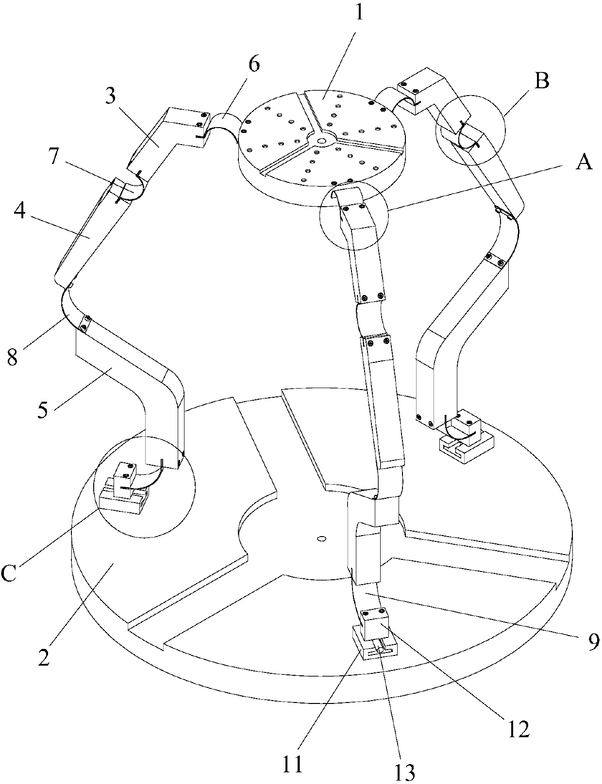
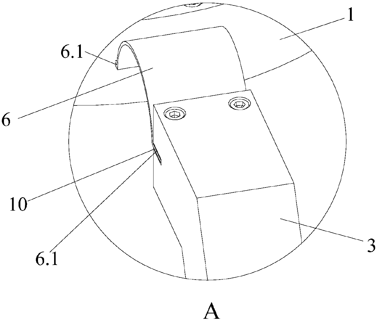
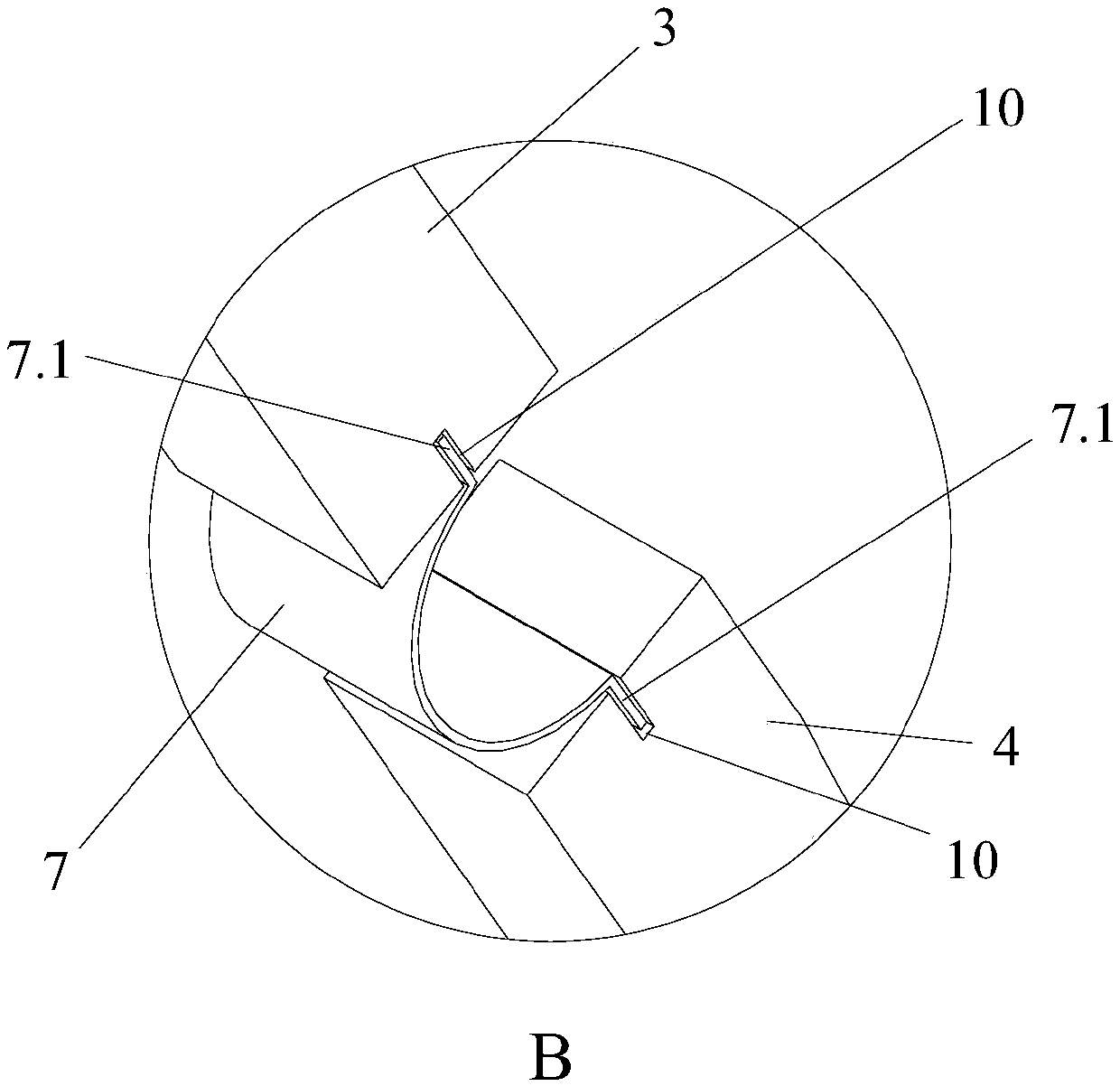
[0029] Such as Figure 1 to Figure 4 As shown in Fig. 1, a new type of large-stroke compliant parallel micro-positioning platform includes a moving platform 1, a fixed platform 2, a driving device set on the fixed platform 2, and three kinematic branch chains for connecting the fixed platform 2 and the moving platform 1, wherein , the moving platform 1 is located above the fixed platform 2, and the three moving branch chains are evenly distributed on the side of the moving platform 1. One end of each moving branch chain is connected to the driving device, and the other end is connected to the moving platform 1. Each moving branch chain is composed of Composed of rigid components and compliant joints.

[0030] Each kinematic branch chain of the present invention is made up of rigid component and flexible joint connection means: each kinematic branch chain comprises rigid component one 3, rigid component two 4 and rigid component three 5; Rigid component one 3 and rigid componen...

Embodiment 2

[0037] The only difference between this embodiment and Embodiment 1 is that the compliant parallel micro-positioning platform may include two or more kinematic branch chains for connecting the fixed platform and the moving platform, wherein each kinematic branch chain is composed of rigid components and Composed of supple joint connections. Each kinematic branch chain includes several rigid components, and each rigid component is connected by compliant joints. The rigid components at both ends of each motion branch chain are respectively connected with compliant joints, and the rigid components at both ends of the motion branch chain are respectively connected with the moving platform and the driving device through the compliant joints. The openings of adjacent compliant joints in each kinematic branch chain are opposite.

[0038] The micro-positioning platform of this embodiment adopts two or more than four motion branch chains to realize two-degree-of-freedom or multi-degre...


PUM


Abstract

The invention provides a novel large-stroke compliant parallel micro positioning platform, which comprises a movable platform, a fixed platform, driving devices arranged on the fixed platform, and a plurality of motion branch chains for connecting the fixed platform and the movable platform; the movable platform is located above the fixed platform; the motion branch chains are uniformly distributed on the side part of the movable platform; one end of each motion branch chain is connected with the corresponding driving device, and the other end of each motion branch chain is connected with the movable platform; and each motion branch chain is formed by connecting rigid members and compliant joints. The novel large-stroke compliant parallel micro positioning platform provided by the invention is simple in structure and capable of realizing rotation and up-and-down movement of an operating space, and solves the problem that a working space is limited due to small self deformation of an existing parallel micro positioning platform, so that the deformation of the micro positioning platform is effectively improved to acquire a stoke as long as possible, and the stroke of the movable platform can reach the mm<3> (cubic millimeter) level.

Description

technical field [0001] The invention relates to a micro-positioning platform device, in particular to a large-stroke flexible parallel micro-positioning platform. Background technique [0002] In many mechanical design systems at present, rigid structures are necessary, but in order to obtain the advantages seen in living things, such as prolonging the life of components and reducing assembly, many devices are designed to be both flexible and rigid. Therefore, the use of compliant joints is A way to use flexibility to gain some advantages in mechanical design. On the other hand, the parallel mechanism has been widely used in the field of high rigidity, high precision or large load without a large working space because of its multi-branch mechanism and fixed drive. [0003] With the increasingly important applications of compliant parallel mechanisms in the fields of microelectronics, micromachines and ultra-precision machining, compliant parallel mechanisms are one of the k...

Claims


Application Information

Patent Timeline
IPC IPC(8): F16M11/04F16M11/24B66F7/28B66F11/00
CPCB66F7/28B66F11/00F16M11/043F16M11/24
Inventor 卢清华张幼财
Owner FOSHAN UNIVERSITY
Why Eureka
Try Eureka