
Test device and test method for determining the ratchet effect of straight pipelines under high temperature and high pressure

A high-temperature, high-pressure, and test-device technology that is applied to measuring devices, using repeated force/pulsation force to test material strength, instruments, etc., can solve the problem of finite element analysis software deviation, high-temperature ratchet effect dilemma, and difficulty in accurately obtaining high-temperature ratchet effect of materials Data and other issues to achieve the effect of preventing damage and stabilizing the device

Active Publication Date: 2019-02-05
NORTHEASTERN UNIV LIAONING
View PDF8 Cites 0 Cited by
  • Summary
  • Abstract
  • Description
  • Claims
  • Application Information

AI Technical Summary

Problems solved by technology

At present, the domestic research on the high-temperature ratchet effect of materials is mainly to simulate the ratchet effect of materials at high temperature through normal temperature tests combined with finite element analysis. However, due to the immature development of the high-temperature cycle hardening constitutive model theory, the simulation results of the finite element analysis software There is often a large deviation from the actual situation, and it is difficult to accurately obtain the data of the high-temperature ratchet effect of the material, which cannot provide a data basis for the study of the cyclic hardening constitutive model of the material at high temperature, thus making the study of the high-temperature ratchet effect of the material in trouble

Method used


Image

  • Test device and test method for determining the ratchet effect of straight pipelines under high temperature and high pressure
  • Test device and test method for determining the ratchet effect of straight pipelines under high temperature and high pressure
  • Test device and test method for determining the ratchet effect of straight pipelines under high temperature and high pressure

Examples


Embodiment Construction

[0032] The present invention will be described in further detail below in conjunction with embodiment.

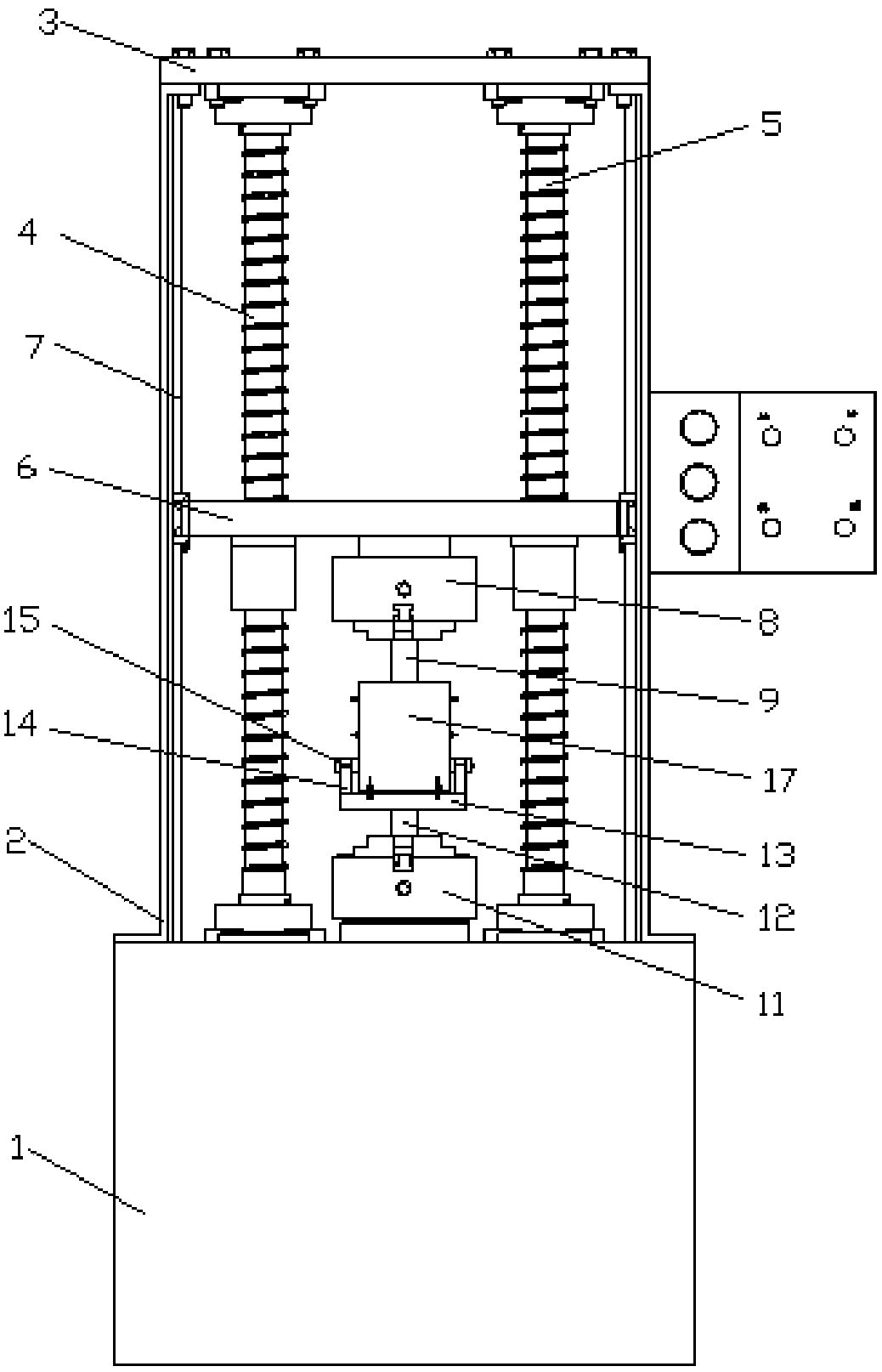
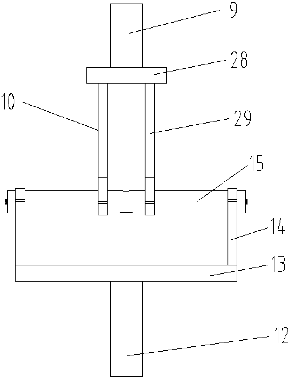
[0033] according to figure 1As shown, a test device for measuring the ratchet effect of straight pipes under high temperature and high pressure, including a base 1, a frame 2 is arranged on the upper part of the base 1, a cover plate 3 is arranged on the upper part of the frame 2, and one end of the first screw 4 and the second screw 5 It is connected with the cover plate 3, and the other end is connected with the base 1. The first screw 4 and the second screw 5 are provided with a first connecting plate 6, and the inner wall of the frame 2 is provided with a slideway 7. The first connecting plate The two ends of 6 are embedded in the slideway 7, so that the first connecting plate 6 slides along the slideway 7, and the upper chuck 8 is fixed on the first connecting plate 6, and the upper chuck 8 is fixed on the first connecting plate. 6 is driven to move up and down, and t...


PUM


Abstract

The present invention is a test device and test method for measuring the ratchet effect of straight pipes under high temperature and high pressure. The device includes a base, a frame is provided on the upper part of the base, a cover plate is provided on the upper part of the frame, and one ends of the first and second screws are connected to the cover plate. , the other end is connected to the base, the first and second screws are provided with a first connecting plate, the upper chuck is fixed to the first connecting plate, the lower chuck is fixed to the base, and a second connection is clamped on the lower chuck column, the upper end of the second connecting column is provided with a support plate, and the sample to be tested is mounted on the support plate. A temperature control box is located around the outside of the sample to be tested. An infrared stress and strain measuring instrument is installed in the temperature control box; A connecting column, the angular connecting piece at the lower end of the first connecting column is clamped on the sample to be tested, and a sealing structure is provided inside the sample to be tested. The displacement data of the corresponding position of the straight pipe is read by the displacement sensor, and the mechanical response parameters of the straight pipe under cyclic load are obtained, and the high-temperature ratchet effect data of the material is obtained.

Description

Technical field: [0001] The invention relates to the technical field of material mechanics testing, in particular to a test device and a test method for measuring the ratchet effect of straight pipelines under high temperature and high pressure. Background technique: [0002] In modern industry, many engineering structures such as aero-engines, aerospace vehicles, nuclear reactors, etc. work under complex loads and complex environments, and many components are in a state of high temperature, high pressure and repeated loading. Because the accidental damage of some of the load-bearing components may have catastrophic consequences, the safety requirements for these components are getting higher and higher, which makes predicting the reliability, safety and life of such systems a hot topic of research by scholars at home and abroad. one. However, the prerequisite for life prediction and safety assessment of components is to obtain the constitutive equation that can accurately ...

Claims


Application Information

Patent Timeline
Patent Type & Authority Patents(China)
IPC IPC(8): G01N3/36G01N3/06
CPCG01N3/068G01N3/36G01N2203/0005G01N2203/0048G01N2203/0075G01N2203/0226G01N2203/0274G01N2203/0682
Inventor 陈小辉王二涛赵二娟赵利王泽宇贾孝玉
Owner NORTHEASTERN UNIV LIAONING
Learn More