Power distribution cabinet

A technology for power distribution cabinets and distributors, applied in substation/distribution device housing, electrical components, substation/switch layout details, etc., can solve problems such as troublesome operation, complicated wiring, and easy exposure of contacts

Inactive Publication Date: 2016-09-21
楼天涯
View PDF5 Cites 0 Cited by
  • Summary
  • Abstract
  • Description
  • Claims
  • Application Information

AI Technical Summary

Problems solved by technology

In the prior art, some manual power-off methods are often used, which often cause troublesome operation and cause hidden dangers in operation
In some automatic power-off methods, because the contacts are on the door body, the electrical wiring and the like occupy the space of the walking path of the cabinet cover, resulting in complicated wiring, and the contacts are easily exposed and easily accessible by the operator, which is not conducive to personal safety. device security

Method used


Image

  • Power distribution cabinet
  • Power distribution cabinet

Examples


Embodiment Construction

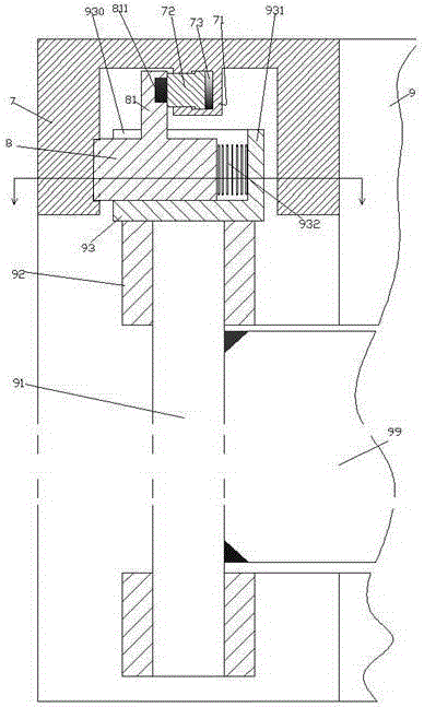
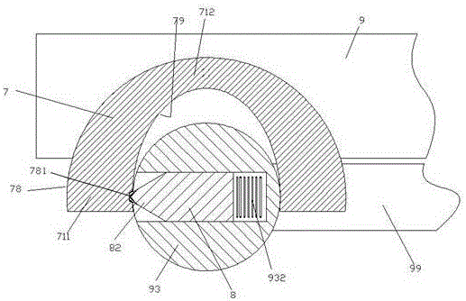
[0008] Combine below Figure 1-2 The present invention will be described in detail.

[0009] The power distribution cabinet according to the embodiment of the present invention is used for distributing electric power from the power supply to the electric load. The rotation of the bearing 92 on the fixed cabinet body 9 is matched to be pivotably installed on the pivot door 99 of the fixed cabinet body 9, and the useful electrical device is installed on the pivot door 99 and is connected to the pivot shaft. 91 is fixedly connected, and the upper end of the pivot shaft 91 is fixedly provided with a cylindrical cap 93 positioned above the bearing 92 and axially positioned by the bearing 92, and the cap 93 is provided with a direction toward A slot 930 that is open on the outside and top and extends along the diameter of the cap body 93 , the on-off operation slider 8 is installed in a sliding fit with the bottom side of the slot 930 and the opposite side facades, The on-off oper...


PUM


Abstract

A power distribution cabinet for distributing power from a power source to an electrical load, the power distribution cabinet device comprises a fixed cabinet (9) for installing power distribution devices, and a pivot shaft (91) and a fixed cabinet The pivoting door (99) of the fixed cabinet (9) is pivotably mounted on the pivoting door (99) by the rotation of the bearing member (92) on the fixed cabinet (9), and the pivoting door (99) is installed on the pivoting door (99). There is an electrical device and is fixedly connected with the pivot shaft (91), the upper end of the pivot shaft (91) is fixedly arranged on the bearing member (92) and axially positioned by the bearing member (92) the cylindrical cap (93).

Description

technical field [0001] The invention relates to the field of power distribution, in particular to a power distribution cabinet. Background technique [0002] In the field of power distribution, it is often necessary to set up a power distribution cabinet to install various power distribution device components to complete the function of distributing power for various power loads. In the power distribution cabinet, some instrumentation and other devices are often arranged on the cabinet body cover, so as to display various power consumption parameters and operation signals for the operator when the power distribution cabinet is working. This is required to power these devices located on the cabinet lid. In order to ensure the safety of use and device maintenance, it is necessary to cut off the power for these cabinet covers when they are in the open state. In the prior art, some manual power-off methods are often used, which often cause troublesome operation and cause hidde...

Claims


Application Information

Patent Timeline
Patent Type & Authority Applications(China)
IPC IPC(8): H02B1/30H02B1/38
CPCH02B1/30H02B1/38
Inventor 楼天涯
Owner 楼天涯
Why Eureka
Try Eureka