Electric signal connector of endoscope

An electric signal and connector technology, applied in the field of endoscopic electric signal connectors, can solve the problems of complex process and high overall cost of the light guide part of the mirror body, and achieve easy assembly and operation, convenient disassembly and operation, and reduced volume Effect

Active Publication Date: 2017-07-28
重庆金山医疗技术研究院有限公司
View PDF9 Cites 4 Cited by
  • Summary
  • Abstract
  • Description
  • Claims
  • Application Information

AI Technical Summary

Problems solved by technology

[0003]In the prior art, there are roughly two types of solutions to realize the electrical signal connection between the mirror body and the image processor, one is to use a standard connecting plug and Design the auxiliary fixing structure, in which the auxiliary fixing structure is realized by pin guiding and locking after rotating at a certain angle. This solution is reliable in electrical signal connection, but the overall cost is high, and there is an additional rotation and locking operation during connection; another solution It adopts the integrated connection structure scheme of the light guide part on the mirror body integrating light guide, air pressure and electric signal, and directly designs the electric signal connection metal shrapnel to the light guide insertion part of the mirror body (such as patent: CN102573607B). This scheme is used by the operator The operation is simple and convenient, but the overall cost is very high, the process of the light guide part of the mirror body is very complicated, and the processing accuracy is required to be higher

Method used


Image

  • Electric signal connector of endoscope
  • Electric signal connector of endoscope
  • Electric signal connector of endoscope

Examples


Embodiment Construction

[0033] Below in conjunction with accompanying drawing and embodiment the present invention will be further described:

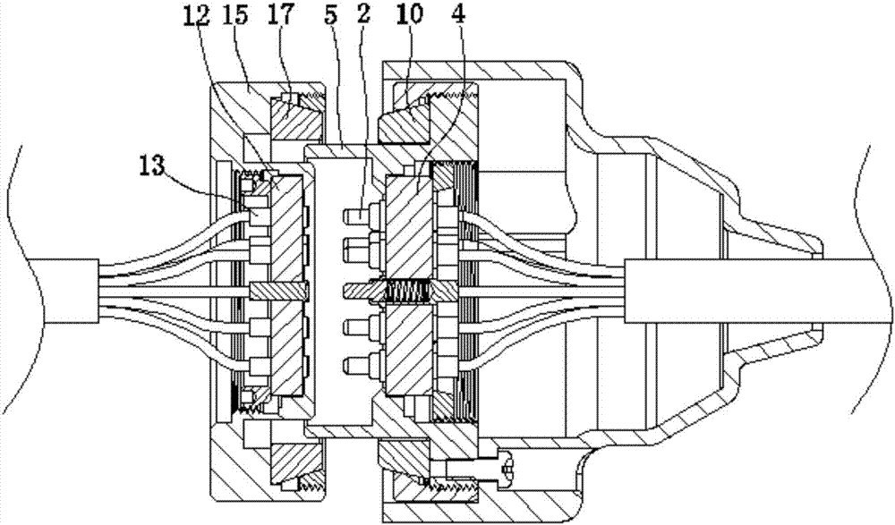
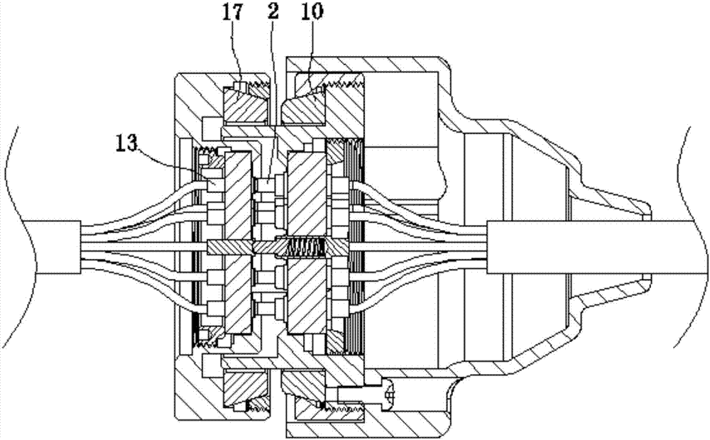
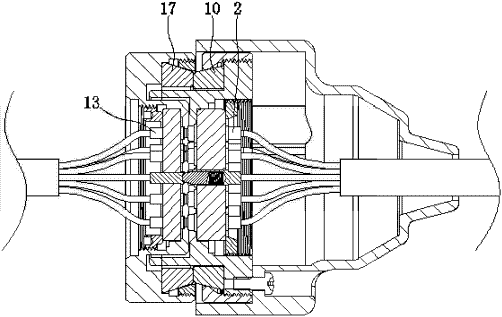
[0034] Such as figure 1 , figure 2 , image 3 , Figure 8 , Figure 9Shown, the present invention is made of two major parts of fixed end assembly and movable end assembly. Wherein, the fixed end assembly is made up of copper column fixing frame 12, conductive copper column 13, fixed end cable 14, main body 15, first fixing ring 16, first permanent magnet 17 and first permanent magnet fixing ring 19, etc., main body 15 It is preferably a ring structure, and a copper column fixing frame 12 is arranged in the inner cavity of the main body 15. The copper column fixing frame 12 is a disc structure, and the outer circumference of the copper column fixing frame 12 is provided with a first plane that acts as a direction indicator. 12a. The edge of the right end of the copper column fixing frame 12 fits with the step of the inner wall of the main body 15, and ...


PUM


Abstract

The invention discloses an electric signal connector of an endoscope. The electric signal connector of an endoscope is formed by a fixed end assembly and a movable end assembly, wherein the fixed end assembly includes a main body; a copper column fixed mount is arranged in the main body; conductive copper columns are arranged on the copper column fixed mount; a ring slot is formed in the right end of the main body; a first permanent magnet is inserted in the ring slot; the movable end assembly includes a housing; a mounting positioning rack is fixedly arranged in the housing; a copper needle fixed mount is arranged in the positioning rack; copper needles or copper needle assembly coordinated with the conductive copper columns; and a second permanent magnet which can be attracted to the first permanent magnet can be arranged between the positioning rack and the housing. The electric signal connector of an endoscope utilizes the principle of opposite poles attract of permanent magnets to realize conduction between the copper needles and the conductive copper columns under the attractive force of the two permanent magnets, and has the advantages of being high in reliability of conduction connection, being simple and compact in structure, being low in production cost, being easy for assembling and operation, and being high in the soundness of mounting of the copper column/copper needle fixed mount so that the copper columns/copper needle fixed mount is not loosened or fallen off.

Description

technical field [0001] The invention belongs to the technical field of medical instruments, and in particular relates to an endoscope electrical signal connector. Background technique [0002] Electronic endoscope system is more and more widely used in medical examination and operation. The video image observed by the operator is the core part of the whole system. The image is collected by the objective lens at the front end of the mirror body and transmitted to the image processor through the cable. The speculum electrical signal connector just plays the electrical signal connection between the scope body and the image processor. [0003] In the prior art, there are roughly two types of solutions to realize the electrical signal connection between the mirror body and the image processor. One is to use a standard connection plug and design an auxiliary fixing structure, wherein the auxiliary fixing structure is guided and rotated by pins. It can be locked after a certain an...

Claims


Application Information

Patent Timeline
Patent Type & Authority Applications(China)
IPC IPC(8): H01R13/62H01R24/20H01R24/28H01R107/00
CPCH01R13/6205H01R24/20H01R24/28H01R2107/00H01R2201/12
Inventor 周健邓安鹏王聪彭永棒
Owner 重庆金山医疗技术研究院有限公司
Why Eureka
Try Eureka