Robot cleaner and operating method thereof

一种自动吸尘器、吸尘器的技术,应用在吸尘器、自动控制行进运动、非电动变量控制等方向,能够解决不能适当地完成清洁操作等问题

Inactive Publication Date: 2005-07-13
LG ELECTRONICS INC
View PDF0 Cites 16 Cited by
  • Summary
  • Abstract
  • Description
  • Claims
  • Application Information

AI Technical Summary

Problems solved by technology

Therefore, it is impossible to take measures against the abnormal travel of the vacuum cleaner, so that the cleaning operation cannot be properly completed

Method used


Image

  • Robot cleaner and operating method thereof
  • Robot cleaner and operating method thereof
  • Robot cleaner and operating method thereof

Examples


Embodiment Construction

[0016] Now, preferred embodiments of the present invention will be described in detail with reference to the accompanying drawings, examples of which are shown.

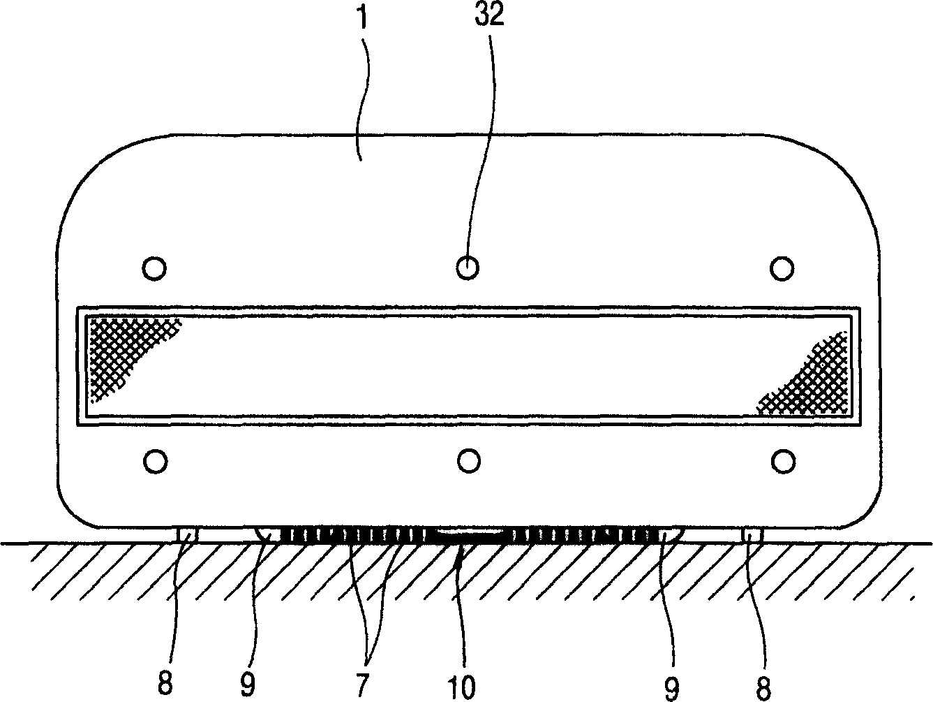
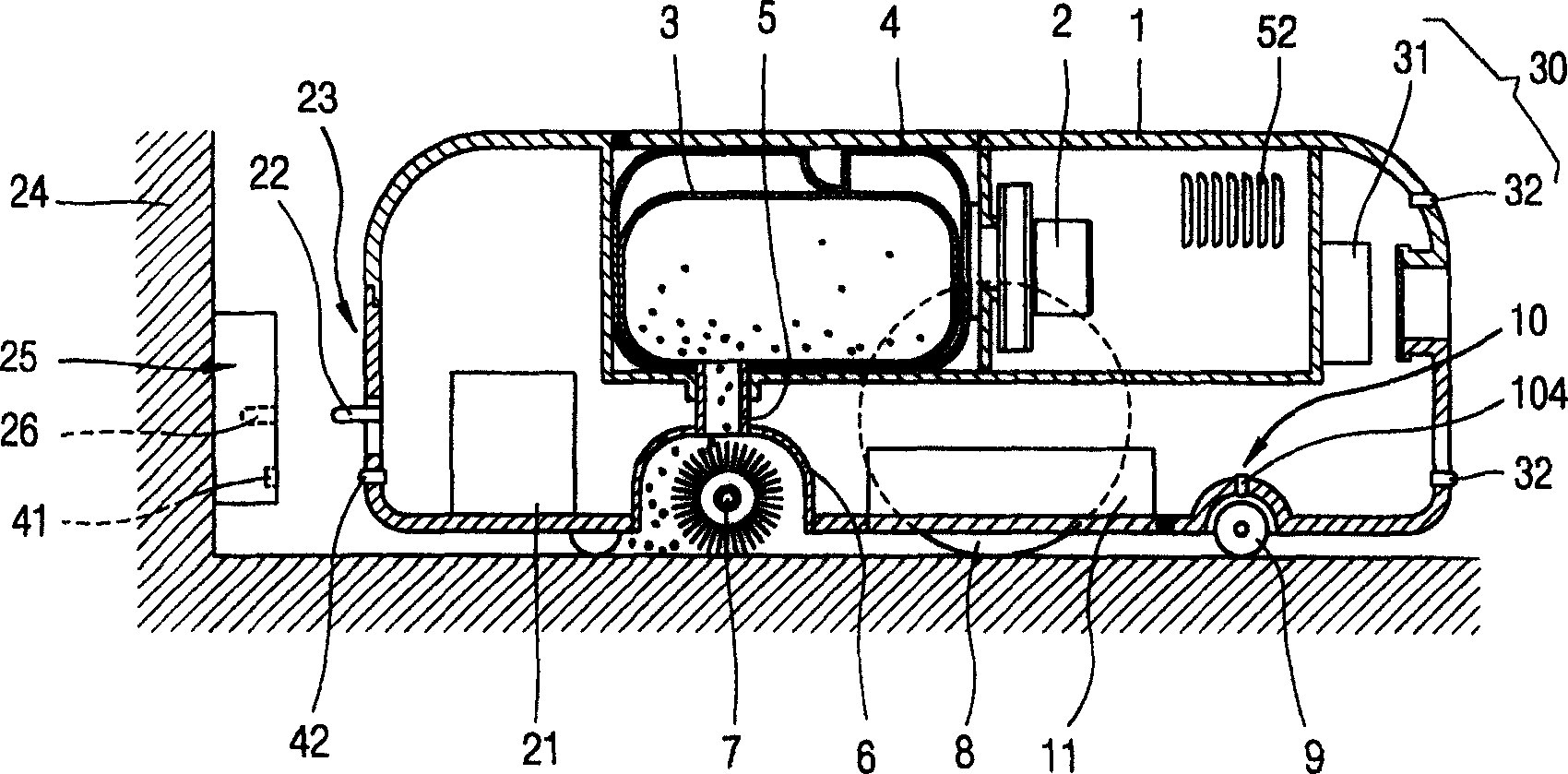
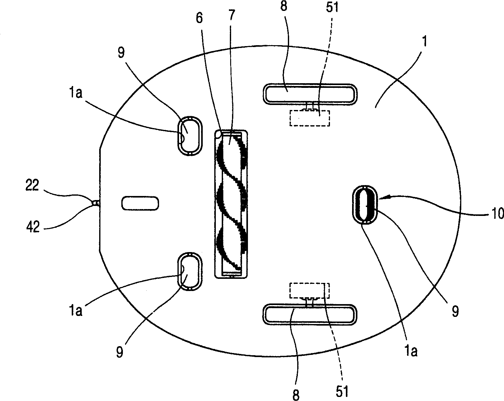
[0017] Such as Figure 1 to Figure 3 As shown, the vacuum cleaner according to the present invention includes: a fan motor 2, which is installed inside the vacuum cleaner body 1 to generate suction; a filter container 4, which has a filter 3 installed near the fan motor 2 and filters the The dirt sucked by the fan motor 2; a suction head 6, which is located at the bottom of the body and is connected with the filter container 4 through a connecting pipe 5, thereby sucking away the dirt on the floor; a brush 7, which is rotatably arranged In the suction head 6, it is used to brush the dirt stuck on the floor; an exhaust port 52 is formed on one side of the body 1, and the filtered air is discharged through the exhaust port 52; at least one navigation Sensor 30, which is installed on one side of the vacuum cleaner body...


PUM


Abstract

An automatic vacuum cleaner, comprising: a suction unit installed in a vacuum cleaner body to suck up dirt on the ground; a drive unit to move the vacuum cleaner body; a wheel installed on the vacuum cleaner body A bottom is in contact with the ground and is rotated by the movement of the vacuum cleaner body; a detection unit is used to detect whether the wheel is rotating; and a control unit is used to control the driving unit in response to a signal from the detection unit. Therefore, the automatic vacuum cleaner can perform the cleaning operation smoothly and continuously despite the abnormal stop of the automatic vacuum cleaner caused by an obstacle not recognized in the previous operation.

Description

technical field [0001] The present invention relates to an automatic vacuum cleaner and its control method, in particular to a vacuum cleaner capable of smoothly completing the cleaning operation by taking appropriate measures when an obstacle or the like causes abnormal movement of the vacuum cleaner during the automatic moving cleaning process and its control methods. Background technique [0002] Generally, an automatic vacuum cleaner is a machine that automatically detects the area to be cleaned, obstacles or the like without human control, cleans while moving automatically, and automatically moves to the charging terminal to recharge when the battery energy is exhausted, And return to the area to be cleaned after charging to complete the cleaning operation. [0003] A conventional automatic vacuum cleaner includes a suction unit to suck up dirt on the floor; a drive wheel connected to a drive motor to move the automatic vacuum cleaner in a moving direction; a plurality...

Claims


Application Information

Patent Timeline
Patent Type & Authority Applications(China)
IPC IPC(8): A47L9/00A47L5/22A47L9/28A47L11/00G05D1/02
CPCG05D1/0225G05D1/0255G05D1/0234A47L2201/04A47L11/00
Inventor 田炯臣任亨彬
Owner LG ELECTRONICS INC
Why Eureka
Try Eureka