Rotatable sputtering target

a rotatable sputtering and target technology, applied in the field of rotatable sputtering targets, can solve the problems of weak joint strength between difficult pressure on the hollow target material, and complicated jointing of the target material and the back tube of the rotatable sputtering target, etc., to increase the tolerance of sputtering power, maintain joint strength, and simplify the production process

Active Publication Date: 2020-06-25
OUMEIDA APPLIED MATERIALS TECH CO LTD +1
View PDF4 Cites 3 Cited by
  • Summary
  • Abstract
  • Description
  • Claims
  • Application Information

AI Technical Summary

Benefits of technology

[0010]According to the aforementioned shortcomings, one objective of the present invention is to simplify the process of producing the rotatable sputtering target. Another objective of the present invention is to both maintain the joi...

Problems solved by technology

However, the technique of jointing the target material and back tube of the rotatable sputtering target is much more complicated than that of the planar sputtering target.
Because applying pressure on the hollow target material is not easy during bonding, joint strength between the target material and the back tube is weak and the target material is prone to be detached at a certain temperature during the sputtering process.
Furthermore, when the solder solidifies, its volume may shrink, causing shrinking stress.
If the detaching area grows to a certain degree, the heat transferring from the target material to the back tube will be dramatically decreased, whic...

Method used


Image

  • Rotatable sputtering target
  • Rotatable sputtering target
  • Rotatable sputtering target

Examples


examples 1 to 4

[0030]First, a back tube with 125 mm internal diameter, 133 mm external diameter and 1500 mm length was provided. The materials of the back tubes used in all Examples and Comparative Examples are listed in Table 1.

[0031]After that, a hollow target material with 142 mm internal diameter, 154 mm external diameter and 700 mm length was formed through sintering, casting, processing, etc. The materials of the target materials used in Examples and Comparative Examples are listed in Table 1. The hollow target material in Example 1 was made of indium tin oxide (ITO) through sintering and processing steps; the hollow target material in Example 2 was made of molybdenum through casting and processing steps; the hollow target material in Example 3 and Example 4 were made of silicon through crystal growth and machining steps.

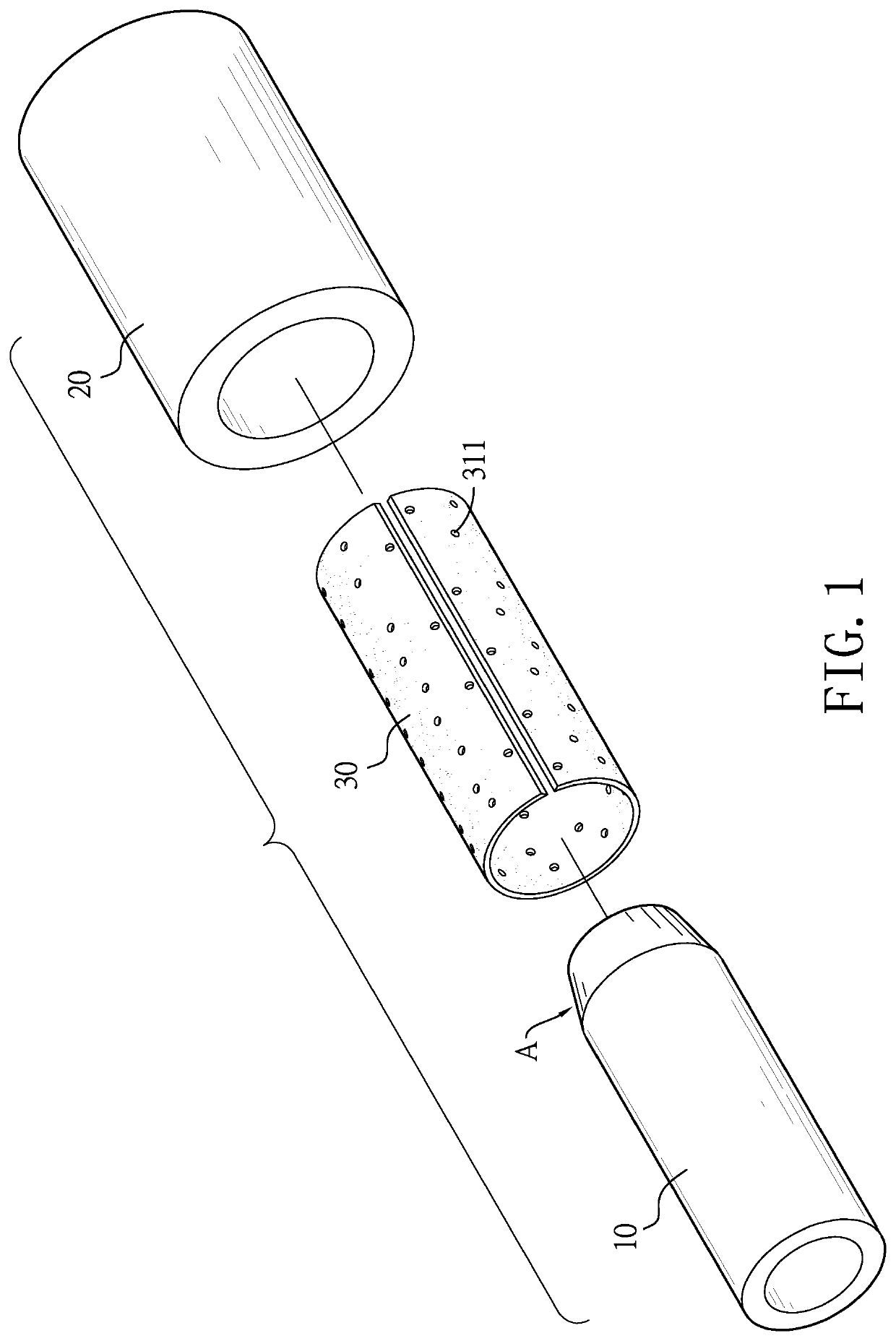
[0032]Then, as shown in FIG. 1, the back tube 10 was installed on an auxiliary tool A before assembly. A graphite blanket 30 was first formed with multiple through holes 311...


PUM

PropertyMeasurementUnit
Electrical resistivityaaaaaaaaaa
Electrical resistanceaaaaaaaaaa
Electrical conductoraaaaaaaaaa

Abstract

A rotatable sputtering target has a target material, a back tube and a joint piece. The joint piece is disposed between the target material and the back tube. The joint piece has a compressible structure and an electrically and thermally conductive adhesive. Particularly, the compressible structure being a compressible blanket or a compressible sheet has multiple through holes and thus the electrically and thermally conductive adhesive is filled in the through holes and then directly formed between the target material and the back tube. Using the joint piece to joint the target material and the back tube not only maintains the joint strength but also elevates the tolerable power of the rotatable sputtering target, which can increase the sputtering efficiency.

Description

BACKGROUND OF THE INVENTION1. Field of the Invention[0001]The present invention relates to a sputtering target, more particularly to a rotatable sputtering target.2. Description of the Prior Arts[0002]Magnetron sputtering utilizes a magnetic control apparatus to change the movement of the electrons in the plasma via electromagnetic effect and therefore increase the ionization rate and sputtering efficiency. When a planar sputtering target is sputtered by conventional magnetron sputtering, the sputtering will be focused on the surface area that has the strongest tangent magnetic field and cause a track-like erosive surface on the target, which decreases the usage of the planar sputtering target to 35% to 50% during the magnetron sputtering process.[0003]In order to solve the problem occurring on magnetron sputtering the planar sputtering target, a rotatable sputtering target is used. As disclosed in TW 1534283, an uniform erosive surface may be obtained by magnetron sputtering the ro...

Claims


Application Information

Patent Timeline
IPC IPC(8): H01J37/34C23C14/34
CPCH01J37/3429H01J37/3417H01J37/342H01J37/3497H01J37/3435C23C14/34H01J37/3423C23C14/3407
Inventor WU, I-SHENG
Owner OUMEIDA APPLIED MATERIALS TECH CO LTD
Why Eureka
Try Eureka